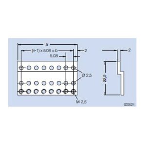
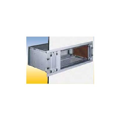
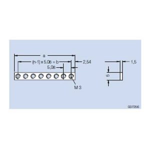
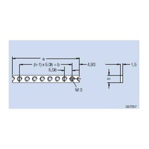
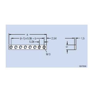
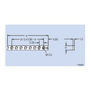
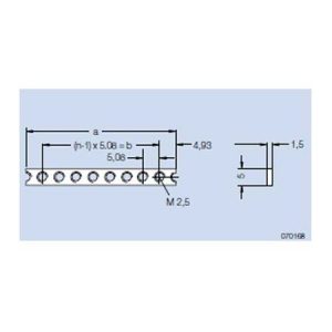
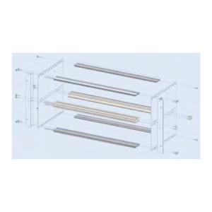
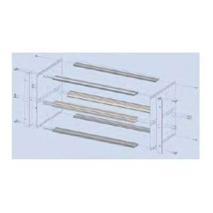
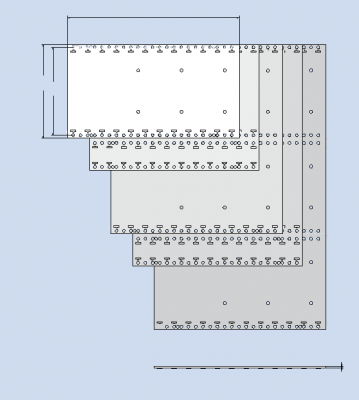
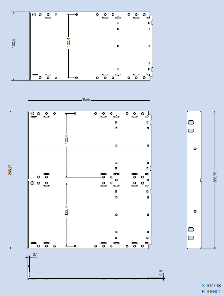
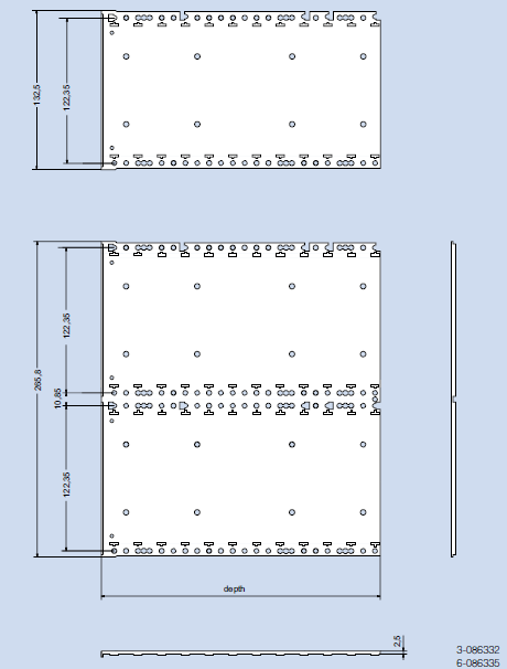
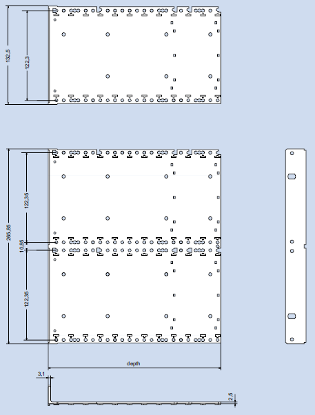
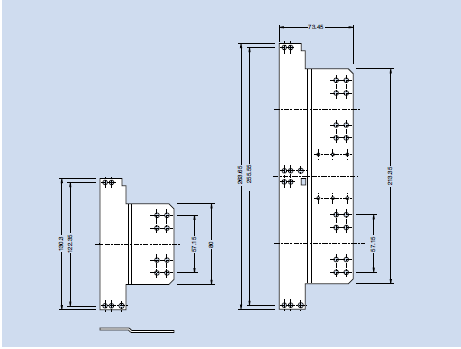
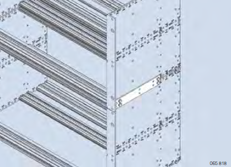
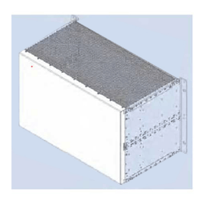
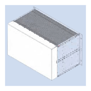
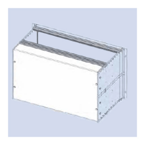
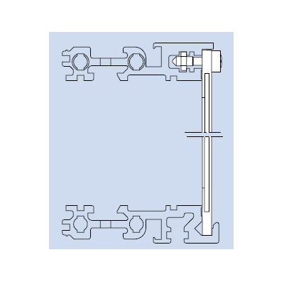
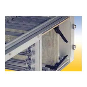
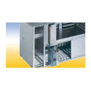
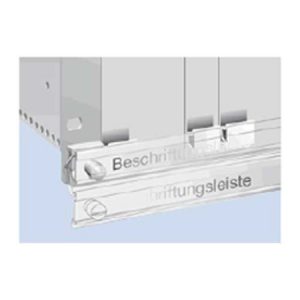
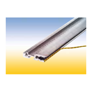
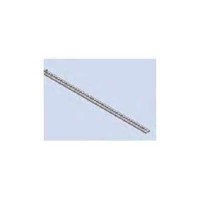
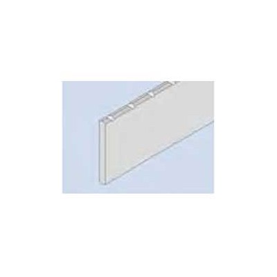
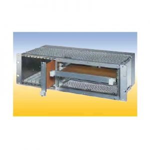
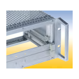
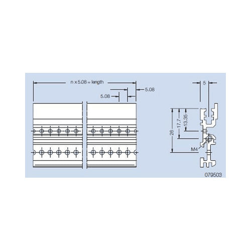
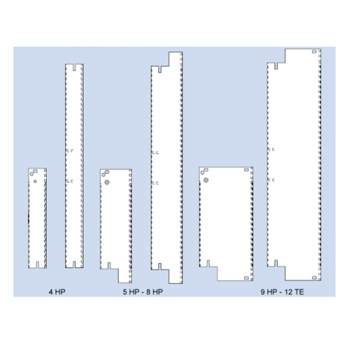
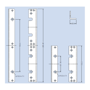
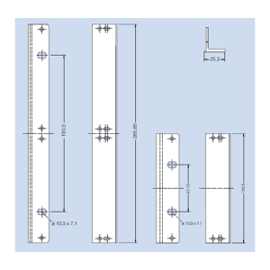
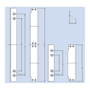
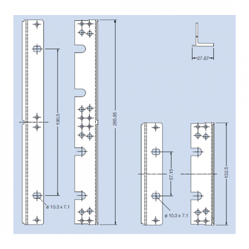
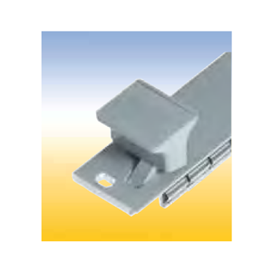
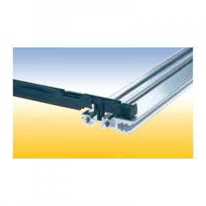
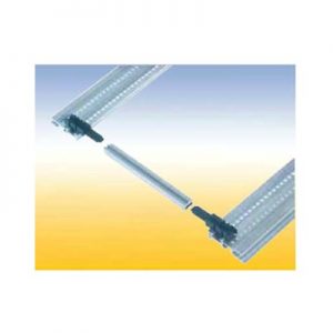
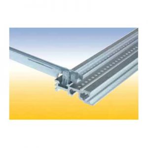
 Subrack Divider Kit 2 x 3 U - 42 HP and 6 U - 40 HP The divider separates a 6 U subrack into a field for 6 U PCB’s and 2 fields of 3 U. Finish: colorless chromated Delivery: 1 double front profile 2xVE1 43 HP chromated 1 double rear profile 2xHK 43 HP anodized 2 divider strips Assembly: Mounting parts
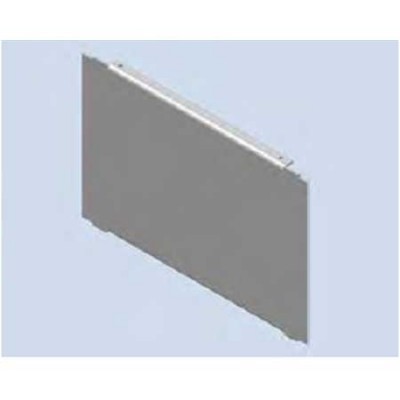
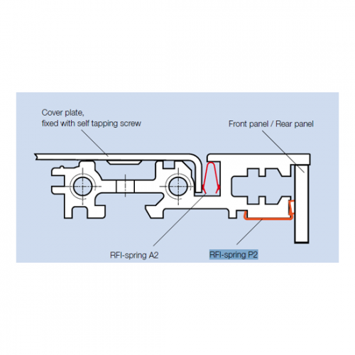
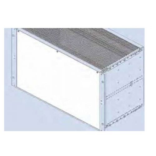
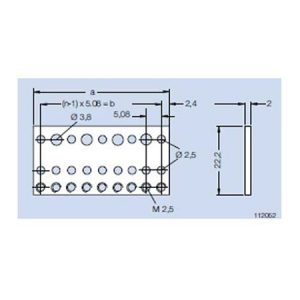
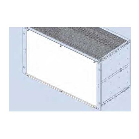
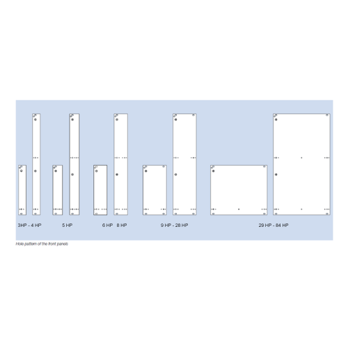
 Plug-in Front Panel 85 HP The front panel bottom edge is inserted in the groove of a specially profiled rail. With slits in the side edges for insertion of RFI springs. To be used in combination with below mentioned flanges only. Finish: front side anodized, rear side conductive Delivery: 1 front panel 3 grounding bushing M 2.5 3 crosshead screw M 2.5 x 11.3
 20 HP for horizontal mounting of 6 U PCB‘s in 3 U subracks. The horizontal mounting frame needs 52 HP in the width. For 84 HP subracks are available Placed right: 52 HP for horizontal mounting frame, 32 HP for 3 U PCB‘s Placed left: 52 HP for horizontal mounting frame, 1 HP for air and leakage paths, 31 HP for 3 U PCB‘s.
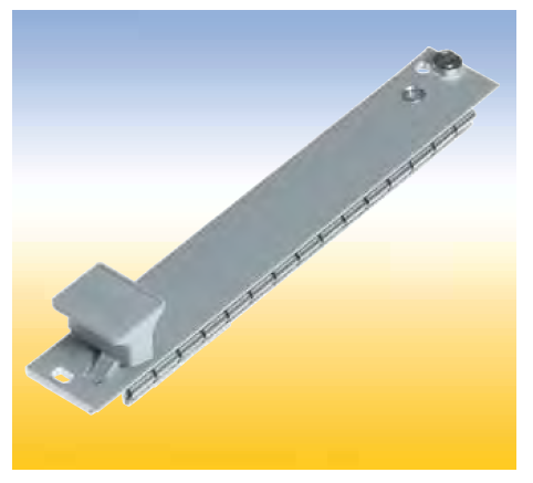
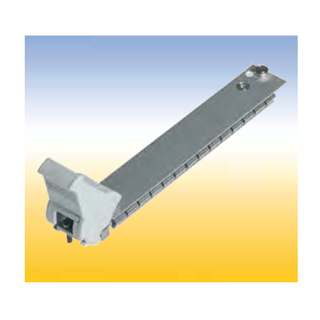
 Hinged Front Panel 85 HP With slits in the side edges for insertion of RFI springs. The hinge is screwed to the profiled rail of the subrack. An 84 HP threaded strip is needed. To be used in combination with below mentioned flanges only. Finish: front side anodized, rear side conductive Delivery: 1 front panel 1 hinge 3 grounding bushings Mounting parts Delivery: as unassembled kit. Assembled kits on request.
 For assembly on a PCB. Handle and front connector are screwed on the front panel. The plain front panel is easy to modify. Four versions are available: 1. Flat front panel blank The front side is covered with a removable transparent foil. 2. Flat front panel anodized Front anodized, rear conductive. 3. Flat front panel RFI Front anodized, rear conductive. With slits in the side edges for insertion of RFI springs. 4. Extruded front panel RFI Made of extruded aluminum alloy, with slits in the side edges for insertion of RFI springs for contact. Surface finish is colorless chromated.
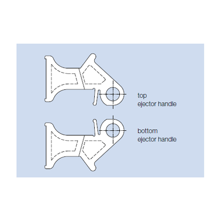
 Front Panels with Ejector Handle For easy release of PCB’s with high pin connections. The ejector handle is extends through the front panel and is screwed together with the bearing bushing at the front connector. Four versions are available: 1. Flat front panel blank. The front side is covered with a removable transparent foil. 2. Flat front panel anodized. Front anodized, rear conductive. 3. Flat front panel RFI Front anodized, rear conductive. With slits in the side edges for insertion of RFI springs. 4. Extruded front panel RFI Made of extruded aluminum alloy, with slits in the side edges for insertion of RFI springs for contact. Surface finish is colorless chromated.
 Front Panels with IEEE Handle For easy pull of PCB’s with high density connectors accordance specification IEEE 1101.10. The assambled handle kit is stuck in the milled space of the front panel and is secured with a clamped spring. Afterwards the PCB are screwed on the intergrated front connector. Two versions with IEEE handle are available: 1. Flat front panel RFI Front anodized, rear conductive. With slits in the side edges for insertion of RFI springs. 2. Extruded front panel RFI Made of extruded aluminum alloy, with slits in the side edges for insertion of RFI springs or for contacting. Surface finish is colorless chromated.
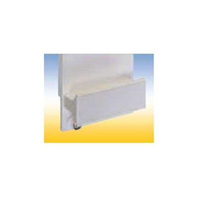
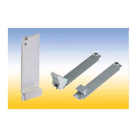
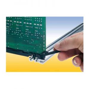
 Card Guide with integrated push and pull assist This special card guide with an integral small lever aids in the handling of PCB’s with high pin plug in connectors. The lever is supported by the walls of a special guide chamber when the board is pulled out or pushed in. It is suitable for a spring to contact a track near the PCB edge. This card guides are snapin and can be secured with screws.
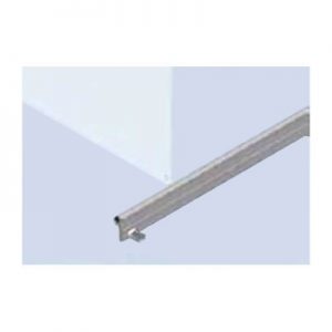
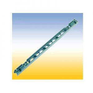
 Lattice construction for heavy mechanical loads. With a provision for a spring to contact front panels and for contacting a track near the PCB edge. This card guides can be snapped in and/or secured with screws. Two versions: 1. With pressed-in nut M 2.5 for assembly to the horizontal rail with oval head screws M 2.5 x 12 2. Without a nut, but one can be added in the existing hexagonal molding.

