 The InterMeZo housing from Intermas is a modular and cost effective housing solution for high quality industrial electronics in a visually attractive design, developed for the highest possible flexibility and simplest possible assembly, with expansion capabilities for more deman ding needs, compliant with stringent EMI/ESD protection specifications, and with extensive configuration options to fulfil application specific requirements. Versions The InterMeZo housings are available to assembly 19” or metric subracks. Alternatively, any dimensions for variable applications are possible.
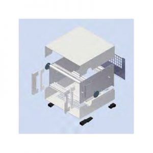
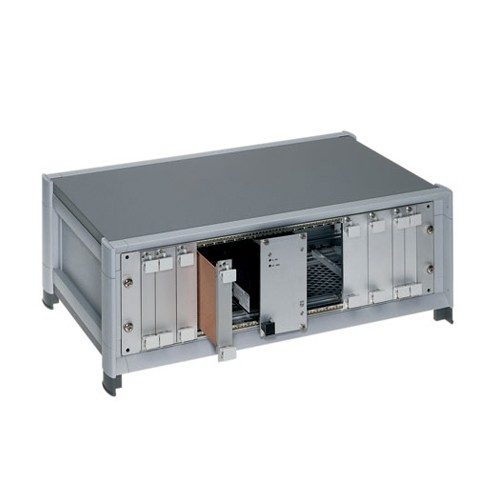
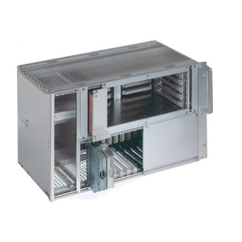
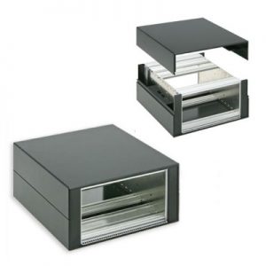
 Description The special design features of the InterCase desktop housing:
- A desktop housing with a simple design for standardized plugin units and individual assemblies.
- The easy to access design allows all covering parts to be removed at any time.
- The bottom cover and the rear panel are provided with louvers.
- The side plates include perforations for attaching profile rails at different board depths.
- The comprehensive range of Intermas subrack accessories allows individual configuration of the desktop housing.
- Can be RFI-shielded.
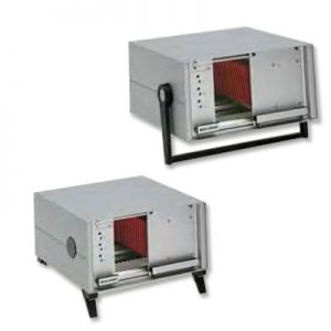
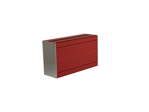
 The InterLock desktop housing has been designed to cover subracks. Also System-Module can be dressed up. The special design features of the InterLock desktop housing:
- The covering elements are formed from recyclable polystyrene plate-material warmly and the joints are welded together by means of a chlorine carbon solution coldly.
- Material strength of 4 to 10 mm can be processed according to demand of the device.
- Easy assembly or disassembly of the case shells. Both case shells are locked by a clamp groove without screws.
- The case is upgradeable by feet and handles.
- However, on account of an economic manufacturing technology special dimensions or special colors can be also already realised for small quantities at a reasonable price.
- Extensive range of accessories is available.
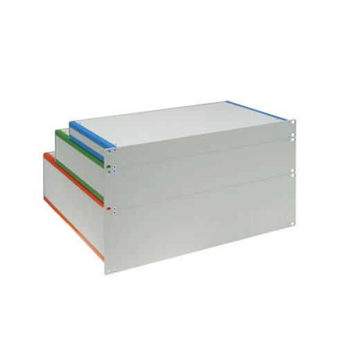
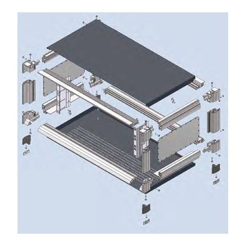
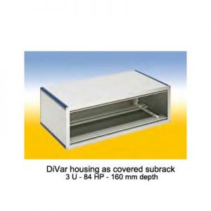 The special design features of the DiVar housing:
- It consists of profiles into which aluminum, sheet steel, stainless steel or plastic panels with a thickness of 1.5 to 2.5 mm are inserted and, if desired, secured with screws. A wall panel at the rear and a panel at the front are screwed to the profiles.
- The flexible design allows variable configuration of the housing geometry in all three axes, this allowing adaptation of the housing to customer specific requirements.
- Different surfaces can be selected for an individual appearance.
- The proven RFI contact spring concept ensures optimum RFI shielding.
- Rails with threaded holes can be pressed into the profile grooves, for example to screw in PCBs or mounting plates.
- The extensive range of Intermas accessories allows unrestricted configuration and installation of both standardized and non-standard components.
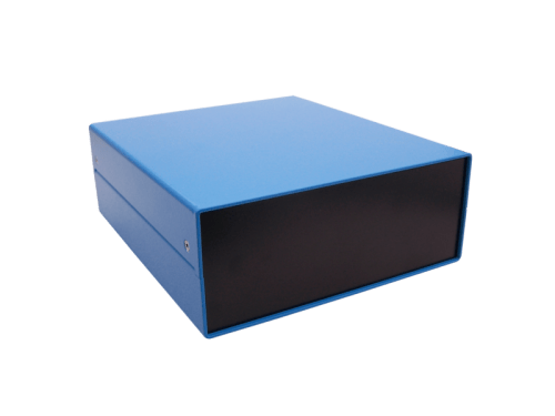

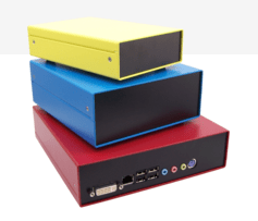
 The flexible aluminium housings for small form factors are characterised by following properties:
- customized adjustments
- quick and uncomplicated mounting
- appropriate for packaging of small electronic units like
- - euroboards
- - customized electronic
- - mITX Boards.
- protection up to IP67
- a wide range of colours for a finish
- additionally printing as customer requirements are possible
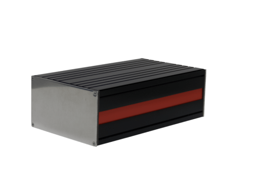 The dust- and hose-proof small casing InterShell IP allows customized electronic applications with following attributes.
- custom specific adjustments
- quick ans und uncomplicated installation
- appropriate for:
- table-top housing for measuring and testing systems
- small case for customized applications
- mobile enclosures for external using
- protection class IP 65
- individual colour design.

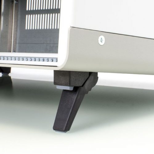
 Feet Kit: 2 feet with tip-up 2 feet without tip-up 4 self-tapping screws Material: Ultramid Purchase Online: 409-059-640-Q10 Feet Kit Package
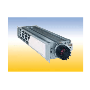 For cooling of 160 mm deep modules. Fan for cooling of 220 mm deep modules on request.
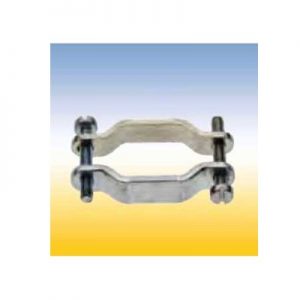 Consists of: 2 brackets and mounting parts Material: metal For housing styles C,D, F, H order no.: 409. 034 532 For housing style E order no.: 409. 034 533
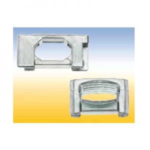 Consists of: 2 brackets and mounting parts Material: zinc die-cast Finish: metallized
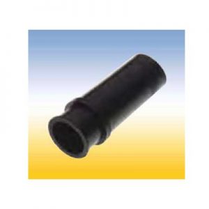 Material: black rubber for housing styles C, F, B order no.: 409. 032 766 for housing style E order no.: 409. 032 767
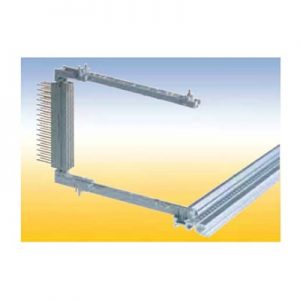 For easy screwless snap-on mounting of connectors accordance to IEC 60 603/ DIN 41 612. With a provision for a spring to contact front panels and for contacting a track near the PCB edge. This snap-in card guides can als be secured with screws.
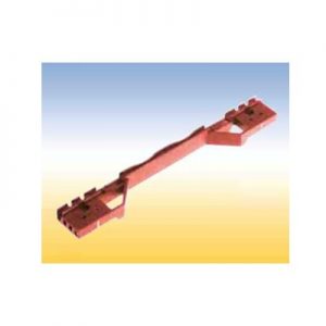 This card guide is in accordance to specification IEEE 1101.10. The required coding of the IEEE is integrated in the card guide head. With provision for the IEEE contact spring for groun ding of the alignmentpins of the PCB‘s front panel. Also with a provision for contacting a track near the PCB edge. This snap-in card guides can be secured with screws.
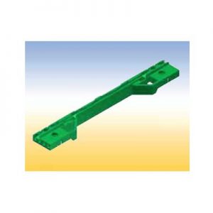 This card guide is also in accordance to specification IEEE 1101.10. For CompactPCI-power supplies and for Plug-in units fitted with SMD. With provision for the IEEE contact spring for grounding of the alignment pins of the PCB‘s front panel. Also with a provision for contacting a track near the PCB edge. This card guide is secured with screws.
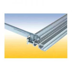 This is an all purpose card guide with provision for a spring to contact front panels.
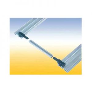 This is a length variable card guide constructed from 3 pieces. The center piece can be cut to any length. With a provision for a spring to contact front panels. These snap-in end pieces can also be secured with screws.
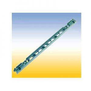 Lattice construction for heavy mechanical loads. With a provision for a spring to contact front panels and for contacting a track near the PCB edge. This card guides can be snapped in and/or secured with screws. Two versions: 1. With pressed-in nut M 2.5 for assembly to the horizontal rail with oval head screws M 2.5 x 12 2. Without a nut, but one can be added in the existing hexagonal molding.
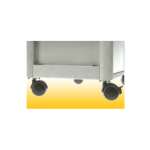 Kit consists of: 2 mounting angles 4 castors Installation hardware
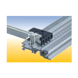 Snapped on the head of standard card guides to comply to the requirements of the specification IEEE 1101.10 Functions: 1. Holding the IEEE contact spring for grounding the alignment pins of the front panel. 2. Adapting the IEEE coding pin. 3. Guiding the 1.6 to 2.4 mm thick PCB.
 with 16 possibilities consists of: 4 coding elements and mounting parts
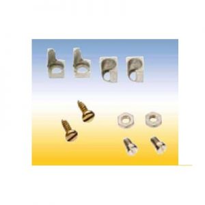 with 32 possibilities consists of: 4 coding elements and mounting parts
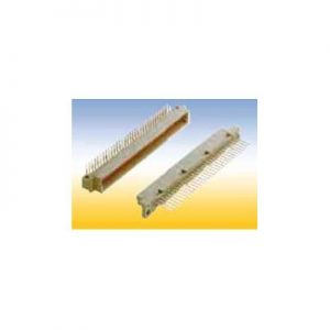 Connectors style B
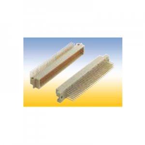 Connectors style C
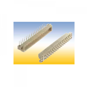 Connectors style D
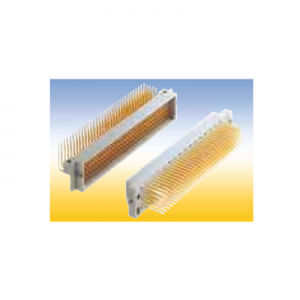 Connectors style E
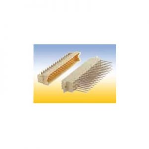 Connectors style F
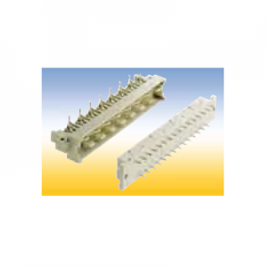 Connectors style H
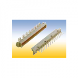 Connectors style R
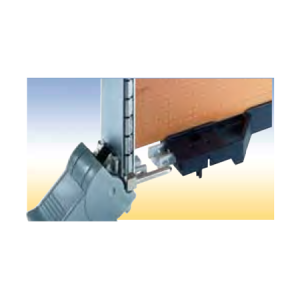 Contact Spring IEEE Snapped into the IEEE card guide or IEEE coding head to ground the alignment pin of the front panel. Material: tin-bronze order no.: 409. 113 450
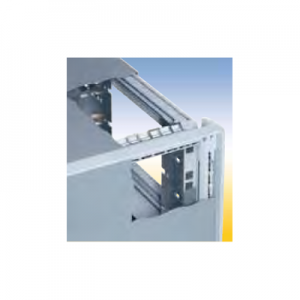 RFI-Shielding Material: stainless steel
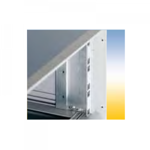 Kit consists of: 2 unit supports and Installation hardware
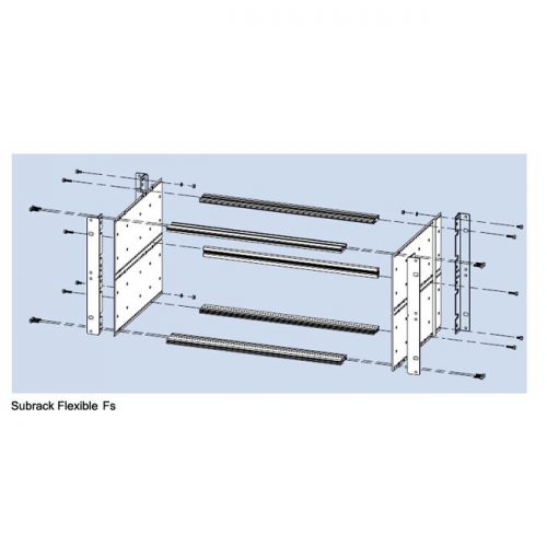
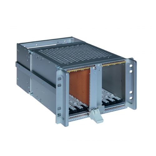
 The special design features of the subrack FLEXIBLE:
- For mounting of the profile rails the side wall is perforated with a grid of 10 mm to allow installation of modules in depth steps of 10 mm. This results in a flexible amount of free space behind the wiring level or in front of the operating level.
- The profile rails are connected to the side wall at the front using a special screw which ensures electrical bonding of the parts via a ring cutter under the head.
- The front and rear profile rails can be interchanged such that the wiring level which is normally at the rear can be implemented at the front of the subrack.
- The extensive range of accessories allows individual configuration.
- Fast and simple assembly: Easy positioning of the profile rails thanks to raised embossing on the side wall.
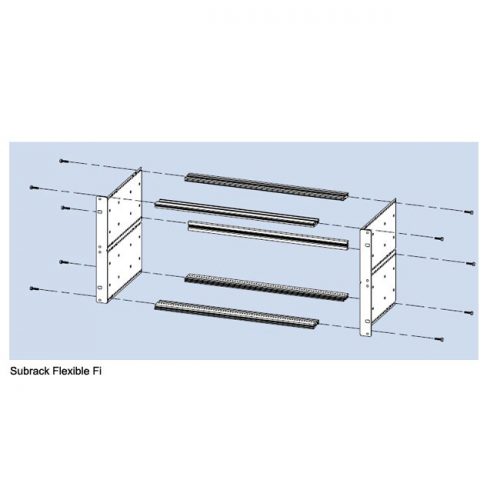 The FLEXIBLE Fi Subrack (with an integrated flange) The combination of the side wall and mounting flange form a single unit. This is the simple and cost effective version. This standard version can not be shielded.
 The FLEXIBLE Fs Subrack (with a separate flange) The side wall and flange are separate components so the flange can be screwed to the side panel at the front or the rear.
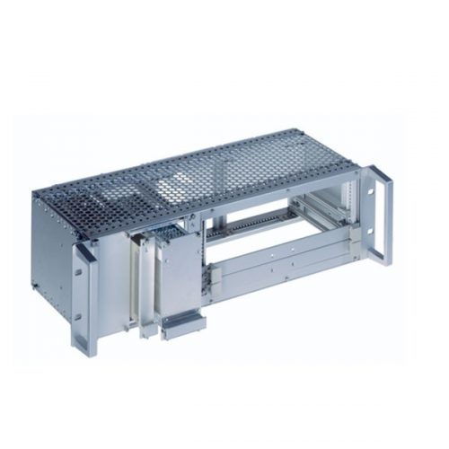
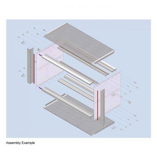 The system dimensions of the RFI- SHIELDED subrack are based on those of the FLEXIBLE subrack as a logical further development to produce the perfectly shielded subrack. This allows unrestricted use of the extensive and complete range of accessories. The special design features of the RFISHIELDED subrack: • The refined RFI shielding concept enables high shielding effectiveness. • The stable stainless steel contact springs ensure permanent and reliable bonding, even after a large number of plug-in cycles. • The perforated RFI cover plates guarantee optimal air flow for improved heat dissipation. • The use of high-quality, seawater-resistant aluminum alloys and stainless steel materials removes, for the most part, the need for unnecessary, environmentally harmful surface treatment. THERE ARE 3 VERSIONS OF THIS SUBRACK 1. Subrack RFI-SHIELDED The standard RFI-shielded version. 2. Subrack RFI-SHIELDED IEEE The front is in accordance with IEEE 1101.10. The special profile rail is designed for the use of inser tion and removal handles (optionally with a hot swap function) for overcoming high insertion and removal resistance. The card guides are fitted with mechanical coding systems and special bonding for electrostatic discharge. 3. Subrack RFI-SHIELDED IEEE / Rear I/O The front and the rear are in accordance with IEEE 1101.10/11. This enables insertion and removal of modules with a front panel from both the front and the rear of the subrack.
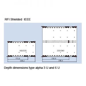 The front is in accordance with IEEE 1101.10. The special profile rail is designed for the use of insertion and removal handles (optionally with a hot-swap function) for overcoming high insertion and removal resistance.
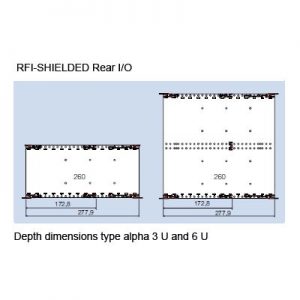 The front and the rear are in accordance with IEEE 1101.10/11. This enables insertion and removal of modules with a front panel from both the front and the rear of the subrack.
 The system dimensions of the InterRail subrack are based on those of the FLEXIBLE Fi as a logical further development to produce a subrack for heavy-duty use. This allows unrestricted use of the extensive range of accessories. The special design features of the InterRail subrack: • Profile rails with a high section modulus guarantee resistance to vibrations. • The refined RFI-shielding concept enables high shielding effectiveness (see the RFI-SHIELDED chapter). THERE ARE FOUR VERSIONS OF THIS SUBRACK: 1. Subrack InterRail Shielding is not possible for the unsealed version. 2. Subrack InterRail RFI The RFI-shielded version. 3. Subrack InterRail RFI - IEEE The front is in accordance with IEEE 1101.10. The special profile rail is designed for the use of insertion and removal handles (optionally with a hot-swap function) for overcoming high insertion and removal resistance. The card guides are fitted with mechanical coding systems and special bonding for electrostatic discharge. 4. Subrack InterRail SNCF & InteRaiI SNCF RNI The special subrack with certification from the French Railways.
 Subrack InterRail RFI The RFI-shielded version. The system dimensions of the InterRail subrack are based on those of the FLEXIBLE Fi as a logical further development to produce a subrack for heavy-duty use. This allows unrestricted use of the extensive range of accessories. The special design features of the InterRail subrack: • Profile rails with a high section modulus guarantee resistance to vibrations. • The refined RFI-shielding concept enables high shielding effectiveness (see the RFI-SHIELDED chapter).
 order no.: 409. 122 300 Consists of: 1 subrack RFI-SHIELDED CPCI / REAR I/O 84 HP, 260 mm nom. depth (160 mm at the front, 80 mm at the rear) for horizontal embedded 6 U PCB’s 1 Backplane 4 Slot, 6 U, 64 Bit, system slot right (1 Slot free e. g. for hard disk or driver) 2 Front panels 6 U - 4 HP (1 at the front, 1 at the rear) 1 ATX 300 W power supply unit with a wide-range input and PFC, with integrated 32 HP Front panel at the front. 1 Fan 1 Pair of card guides red 160 mm (CPU) including IEEE-coding and ESD-spring in the bottom card guide. 1 Pair of card guides red 80 mm (CPU) including IEEE-coding and ESD-spring in the bottom card guide. 4 Pair of card guides black 160 mm (CPU) including IEEE-coding and ESD-spring in the bottom card guide. 4 Pair of card guides black 80 mm (CPU) including IEEE-coding and ESD-spring in the bottom card guide
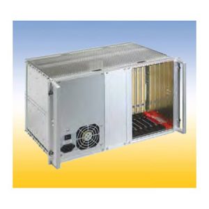 Consists of: 1 Subrack RFI-SHIELDED CPCI / REAR I/O 84 HP, 260 mm nom. depth (160 mm at the front, 80 mm at the rear) 1 Backplane 8 Slot, 6 U, 64 Bit, system slot right 1 ATX 300W power supply unit with a wide-range input and PFC, with assembled front panel. (optional front panel for a drive over the power supply). 1 Blind front panel 16 HP at the front. 1 Blind front panel 4 HP at the front. 1 Blind front panel 48 HP at the rear. 1 Blind front panel 8 HP at the rear. 1 Pair of card guides red 160 mm (CPU) including IEEE-coding and ESD-spring in the bottom card guide. 1 Pair of card guides red 80 mm (CPU) including IEEE-coding and ESD-spring in the bottom card guide. 7 Pair of card guides black 160 mm (CPU) including IEEE-coding and ESD-spring in the bottom card guide. 7 Pair of card guides black 80 mm (CPU) including IEEE-coding and ESD-spring in the bottom card guide.
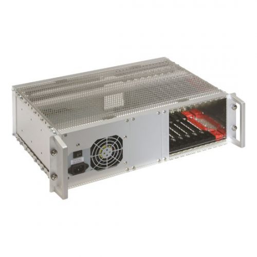 Consists of: 1 Subrack RFI-SHIELDED CPCI / REAR I/O 84 HP, 260 mm nom. depth (160 mm at the front, 80 mm at the rear) 1 Backplane 8 Slot, 3 U, 32 Bit, system slot right 1 ATX 300W power supply unit with a wide-range input and PFC, with assembled front panel. 1 Blind front panel 16 HP at the front. 1 Blind front panel 4 HP at the front. 1 Blind front panel 48 HP at the rear. 1 Blind front panel 8 HP at the rear. 1 Pair of card guides red 160 mm (CPU) including IEEE-coding and ESD-spring in the bottom card guide. 1 Pair of card guides red 160 mm (CPU) including IEEE-coding and ESD-spring in the bottom card guide. 7 Pair of card guides black 160 mm (CPU) including IEEE-coding and ESD-spring in the bottom card guide. 7 Pair of card guides black 80 mm (CPU) including IEEE-coding and ESD-spring in the bottom card guide.
 Consists of: 1 Subrack RFI-SHIELDED CPCI / REAR I/O 84 HP, 260 mm nom. depth (160 mm at the front, 80 mm at the rear) 1 Backplane 8 Slot, 6 U, 64 Bit, system slot right 1 ATX 300W power supply unit with a wide-range input and PFC, with assembled front panel. (optional front panel for a drive over the power supply). 1 Blind front panel 16 HP at the front. 1 Blind front panel 4 HP at the front. 1 Blind front panel 48 HP at the rear. 1 Blind front panel 8 HP at the rear. 1 Pair of card guides red 160 mm (CPU) including IEEE-coding and ESD-spring in the bottom card guide. 1 Pair of card guides red 80 mm (CPU) including IEEE-coding and ESD-spring in the bottom card guide. 7 Pair of card guides black 160 mm (CPU) including IEEE-coding and ESD-spring in the bottom card guide. 7 Pair of card guides black 80 mm (CPU) including IEEE-coding and ESD-spring in the bottom card guide.
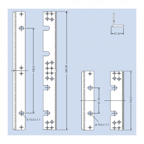 The flange can be mounted to the side panel by means of the mounting screws for the horizontal rails. Material: aluminum, extruded Finish: anodized
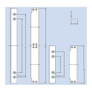 Flange for Wall Mounting For mounting of a subrack on a wall. Material: aluminum Finish: blank, seawater resistant
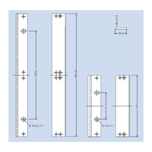 This flange is suitable for mounting of a continous front panel of 85 HP and a hinged front panel of 85 HP in a subrack. The flange will be mounted to the side panel by means of the mounting screws for the horizontal rails. Material: aluminum, extruded Finish: colorless chromated
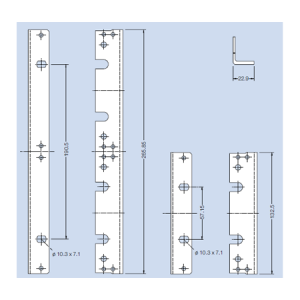 Flange without Nose This flange can be mounted at various depth on the side panel grid. Material: aluminum, extruded Finish: anodized
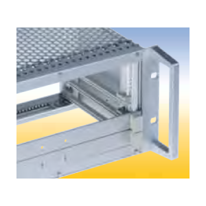 Material: aluminum Finish: anodized
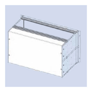 Rear Cover F 84 HP For covering the wiring field of the subrack
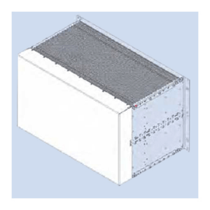 Rear Cover RFI 84 HP Protective wiring rear cover for RFI shielded enclosure. Material: aluminum, 1 mm thick Finish: colorless chromated