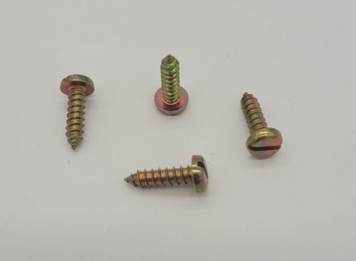
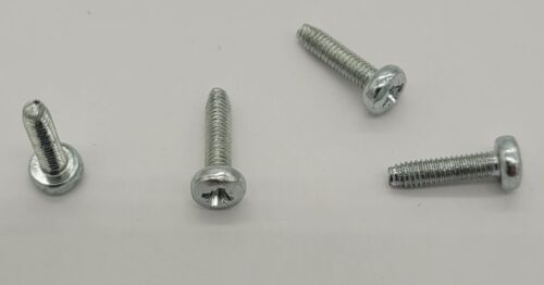
- Screw
- Self tapping
- 2.5-5
- Package qty is 500 pcs per bag
- $.10 each @ 500 pcs per bag.

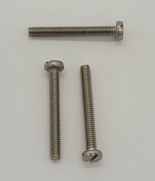
- Screw M2.5x11.3
- Cross head
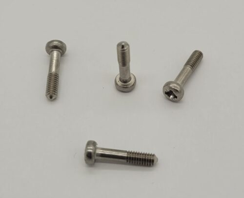
- Captive Screw
- Package qty is 500 pcs per bag
- $0.31 each @ 500 pcs per bag
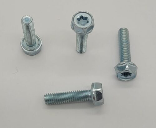

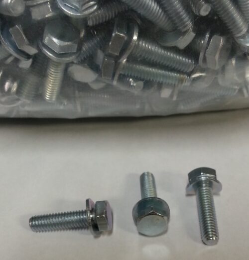
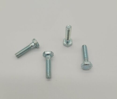
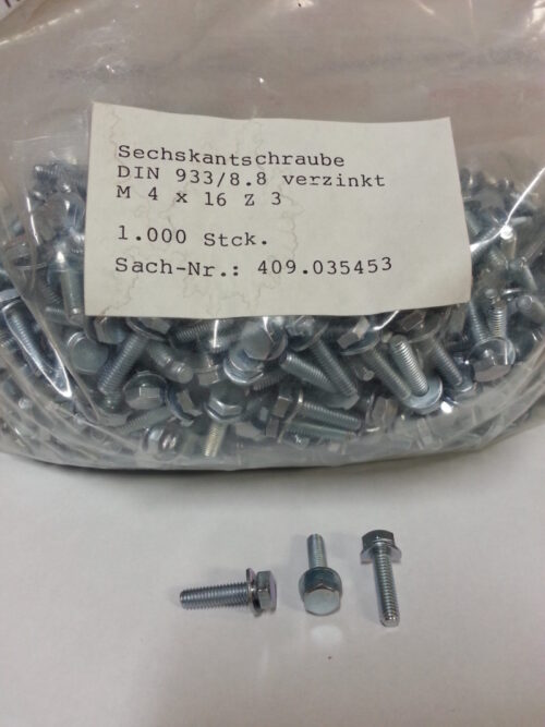
- Screw, M4x16
- 7mm, Torx T20
- Hexagon Head
- Steel, Galvanized, Chromated
- Package qty is 500 pcs per bag
- $.15 each @ 500 pcs per bag.
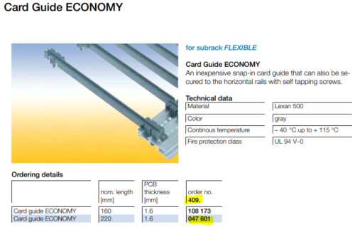

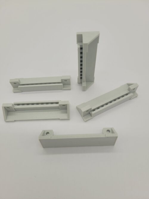
 For subrack FLEXIBLE Card Guide ECONOMY An inexpensive snap-in card guide that can also be secured to the horizontal rails with self tapping screws. Technical data Material Lexan 500 Color gray Continuous temperature – 40 °C up to + 115 °C Fire protection class UL 94 V–0
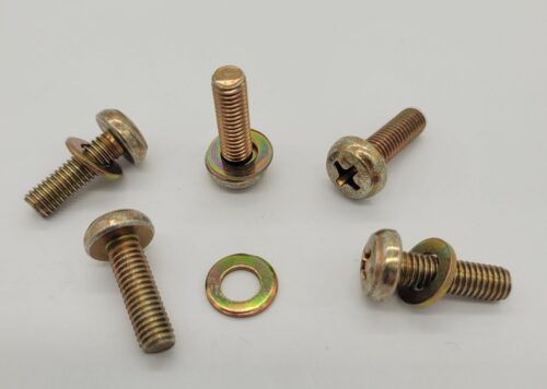

- Screw oval M5-16
- DIN7985
- Pan Head
- Steel
- With Washer DIN125
- Package qty is 100 pcs per bag
- $0.25 each @ 100 pcs per bag
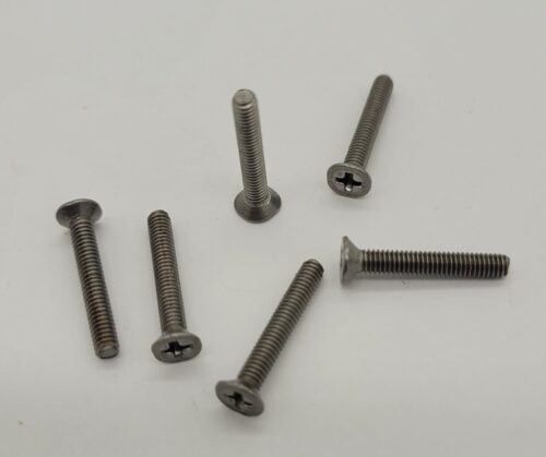

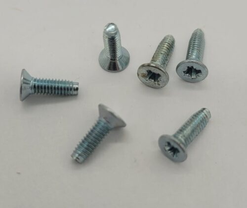
- Screw M2.5x16
- Countersunk
- Cross Head
- Steel
- DIN 965
- DIN 966
- EN 7046-2
- Package qty is 500 pcs per bag
- $0.15 each@500 pcs per bag
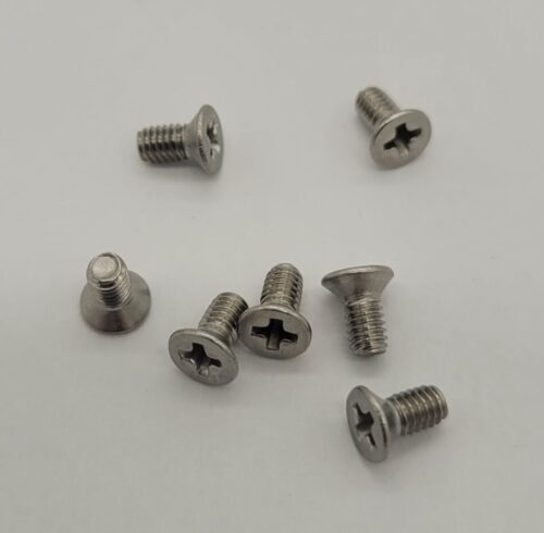

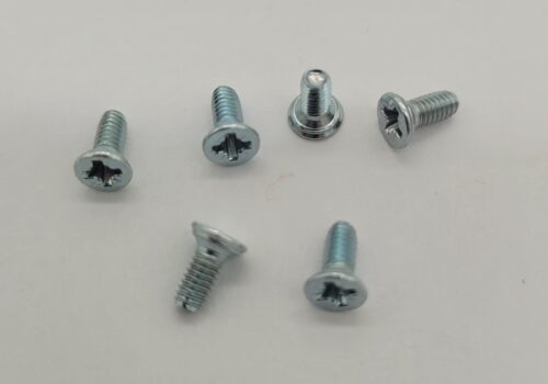
- Screw M2.5x5
- Countersunk
- Cross Head
- Stainless steel
- DIN 965
- Package qty is 500 pcs per bag
- $0.18 each@500 pcs per bag

- Screw M4x16, DIN933
- Hex head, Steel, galvinized, chromated
- DIN933
- Package qty is 500 pcs per bag
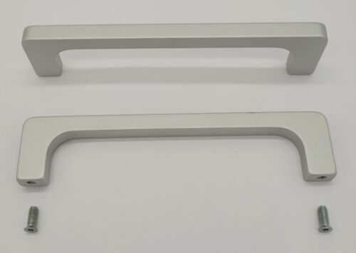

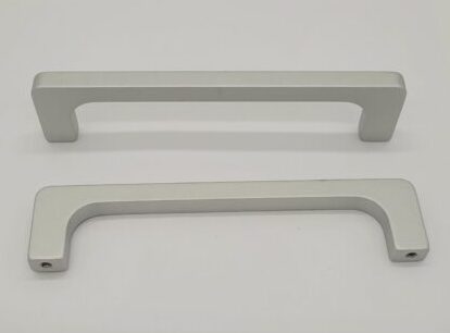
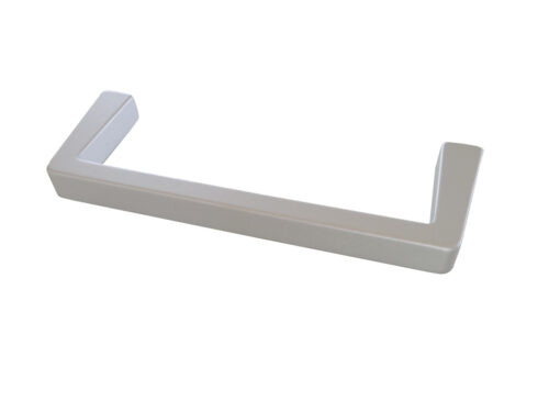
- Handle 3U 32mm L X 30mm D X 8mm W
- Low Profile
- Anodized aluminum
- 2pcs M4x10
- Torx screw countersunk 409-105-789 included with each handle
- Package qty is 10 pcs per bag
- $19.00 each @ 10 pcs per bag.


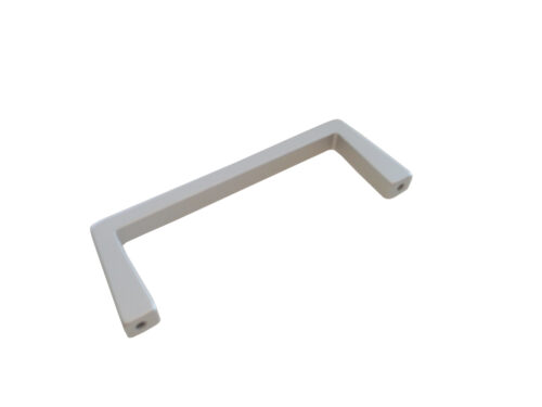
- Handle 6U
- Anodized aluminum
- 2pcs M4x10
- Torx screw countersunk 409-105-789 included with each handle
- Package qty is 10 pcs per bag
- $23.75 each @ 10 pcs per bag.

- Handle 3U
- Anodized aluminum
- 2pcs M4x10
- Torx screw countersunk 409-105-789 included with each handle
- Package qty is 10 pcs per bag
- $19.50 each @ 10 pcs per bag.
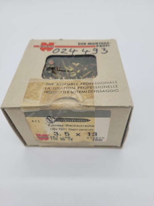


- Screw M3.5x13
- Countersunk, sheet metal
- Stainless steel, galvanized, chromated
- DIN7991
- Package qty is 500 pcs per bag
- $.19 each @ 500 pcs per bag.

- Screw M2.5x8
- Countersunk, self tapping
- Steel, galvanized, chromated
- DIN 965
- DIN 7500
- TAPTITE
- Package qty is 500 pcs per bag
- $.12 each @ 500 pcs per bag.

- Screw M2.5x6
- Countersunk, self tapping
- Steel, galvanized, chromated
- Similar to DIN 965
- Similar to DIN 995
- TAPTITE ISO 7046
- Package qty is 500 pcs per bag
- $.09 each @ 500 pcs per bag.
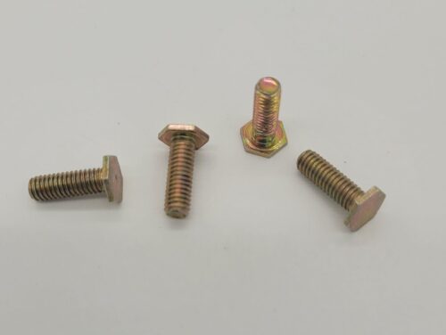

- Screw M4x12
- Hexagon head, .8mm thick head, Similar to DIN933
- Steel, galvanized, chromated
- Package qty is 500 pcs per bag
- $.31 each @ 500 pcs per bag.
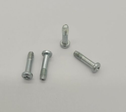

- Screw M3.2X12
- Pan head
- ISO 7045
- Captive Screw
- Package qty is 500 pcs per bag
- $.29 each @ 500 pcs per bag.
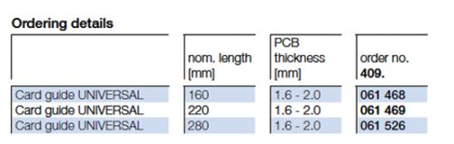

- Card guide
- 1.6-220
- Slide-in
- Package qty is 100 pcs per bag
- $1.49 each @ 100 pcs per bag.
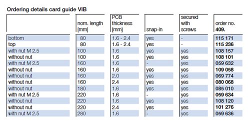

- Card guide
- 1.6-220
- 2.5 nut
- Package qty is 100 pcs per bag
- $1.59 each @ 100 pcs per bag.
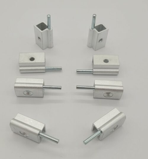

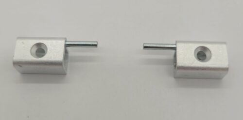
- Hinge Block Kit
- Pair (Left and Right)
- Includes 409-070-510 and 511
- Package qty is 10 kits per bag
- $18 each @ 10 pcs per bag.
- Order with countersunk screw 409-070-521 M2.5x5

- Screw M2.5 x10
- Self tapping screw
- DIN7985
- DIN7500
- steel, galvanized, chromated
- Package qty is 250 pcs per bag
- $.11 each @ 250 pcs per bag.
- Cover plate 84HP-160
- screw on, colorless chromated
- Package qty is 10 pcs per bag
- $18 each @ 10 pcs per bag.

- Side panel BGT-U
- 3U-160 colorless chromated
- Package qty is 10 pcs per bag
- $24.50 each @ 10 pcs per bag.
- Marking plate
- F3 Poly grey
- Package qty is 100 pcs per bag
- $2.75 each @ 100 pcs per bag.
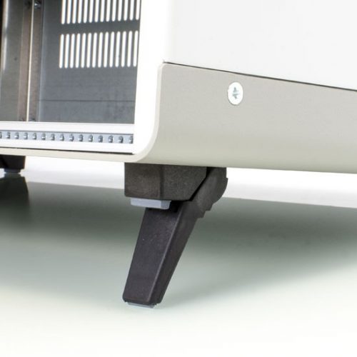

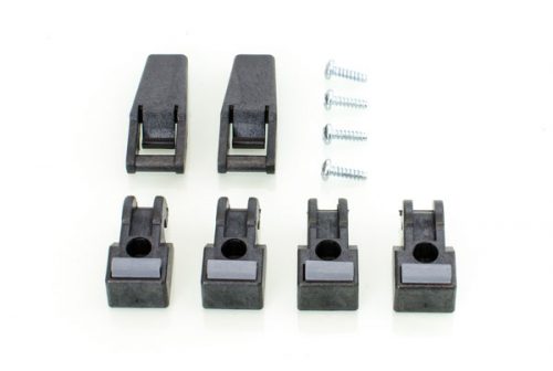
 Feet Kit package includes:
- 2 feet with tip-up
- 2 feet without tip-up
- 4 self-tapping screws
- Color black
- 10 kits per bag priced @ $16 each
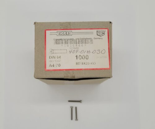


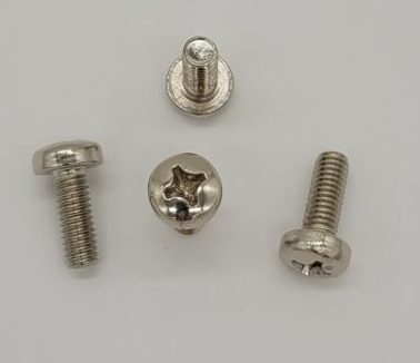
- Screw, M2.5x20
- DIN84
- Pan Head
- Package qty is 500 pcs per bag
- $.31 each @ 500 pcs per bag.

- Screw M6x16
- DIN7985
- Pan Head
- Steel, Nickel
- Package qty is 500 pcs per bag
- $0.18 each @ 500 pcs per bag


- Square nut M2.5, 5x5mm
- DIN562
- steel, galvanized, chromated
- Package qty is 500 pcs per bag

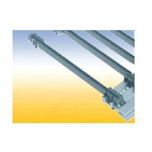
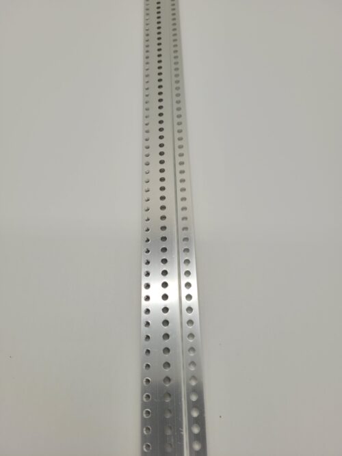
- Z-rail - 84HP
- 425mm long
- M2.5 tap
- 3.8mm holes
- 5 pcs per box

- Z-rail - 84HP
- 425mm long
- M2.5 tap
- 3.8mm & 2.5mm holes
- 5 pcs per box

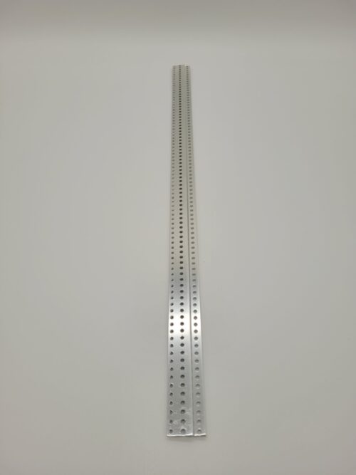
- Z-rail - 84HP
- 425mm long
- M2.5 tap
- 83 holes
- 5 pcs per box
-
- Z-rail - 42HP
- 212mm long
- M2.5 tap
- 41 holes
- 5 pcs per box
-
- Z-rail - 31HP
- 156mm long
- M2.5 tap
- 30 holes
- 5 pcs per box
- Z-rail - 15HP
- 75mm long
- M2.5 tap
- 14 holes
- 5 pcs per box

- Integrated washer!
- 1000 pcs per bag
- 4X16
- DIN 933
- 8.8 Steel plain finish
- Full Thread. $0.18 each @ 1000 pcs per bag
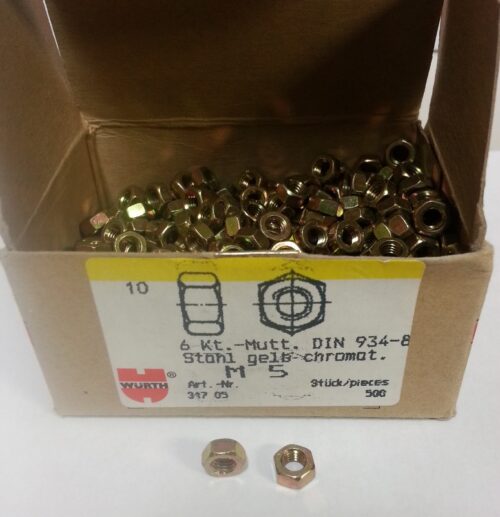

 M5-0.8 HEX Nut,DIN934, steel chromated, 500pcs
- For subrack FLEXIBLE Card Guide ECONOMY An inexpensive snap-in card guide that can also be secured to the horizontal rails with self tapping screws. Technical data Material Lexan 500 Color gray Continuous temperature – 40 °C up to + 115 °C Fire protection class UL 94 V–0 For card guide 1.6-220, see part number 409-047-601
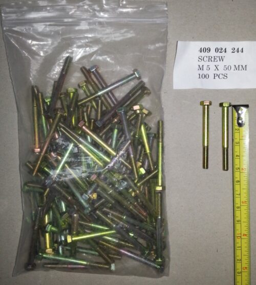
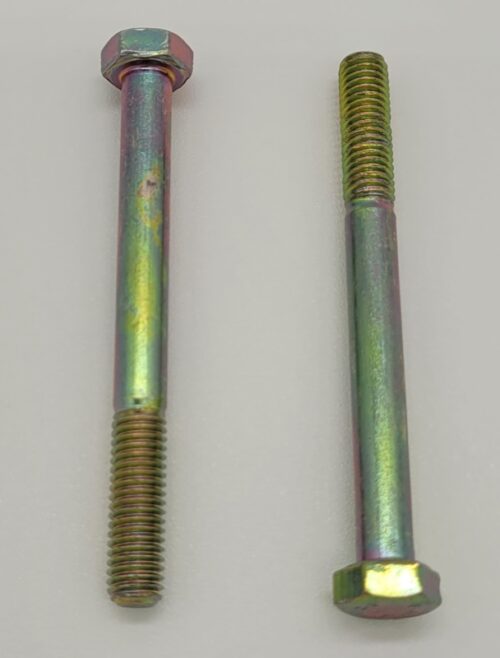
 Hex Screw, M5-0.8 X 50mm, 100 pcs
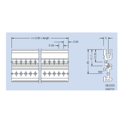
 Contact us directly to purchase this item. Quick Overview Rear Profile HE2 (type delta). Material: aluminum Finish: anodized or colorless chromated
- Quick Overview Rear Profile HE2 (type delta). Material: aluminum Finish: anodized or colorless chromated
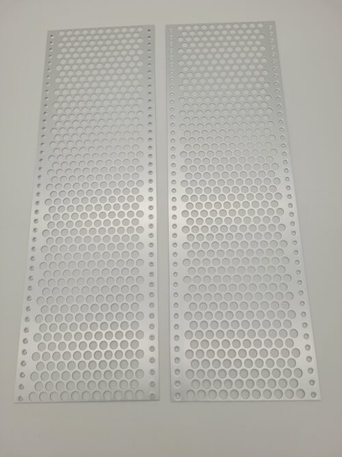
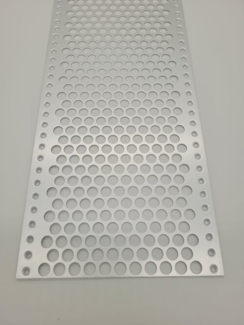
- Quick Overview Hole diameter 4 / 5.2 x 4 mm. The cover plate is mounted with self tapping counter sunk screws on the inside of the side panels. Additionally the cover plate is secured to the horizontal rails by clips. Material: aluminum, 1 mm thick Finish: colorless chromated, seawater resistant
 Quick Overview Rear Profile HE1 (type alpha). Material: aluminum Finish: anodized or colorless chromated
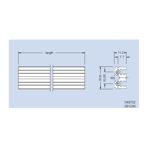 Quick Overview Center Profile ME2 Mounted in the rear of a 6 U subrack (type delta). Material: aluminum Finish: anodized or colorless chromated
 Quick Overview Center Profile MZE Mounted in the rear of a 6 U subrack (type beta), With integrated connector attachment. Material: aluminum Finish: anodized or colorless chromated
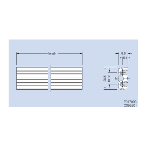 Quick Overview Center Profile ME1 Mounted in the rear of a 6 U subrack (type alpha). Material: aluminum Finish: anodized or colorless chromated
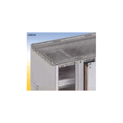 Overview Hole diameter 4 / 5.2 x 4 mm. The cover plate will be mounted with self tapping counter sunk screws outside of the side panels. Additionally the cover plate is secured to the horizontal rails by clips. Material: aluminum, 1 mm thick Finish: blank, seawater resistant
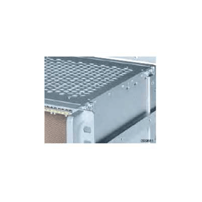 Quick Overview Hole diameter 8.0 mm. The cover plate is mounted with self tapping counter sunk screws at the side panels and at the horizontal rails. Material: aluminum, 1 mm thick Finish: blank, seawater resistant
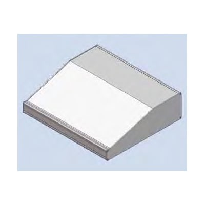 Quick Overview DiVar Desktop Housing with keyboard area Delivery 4 profiles 4 cover plates 2 side plates Assembly hardware
- DiVar Desktop Housing with keyboard area Delivery 4 profiles 4 cover plates 2 side plates Assembly hardware
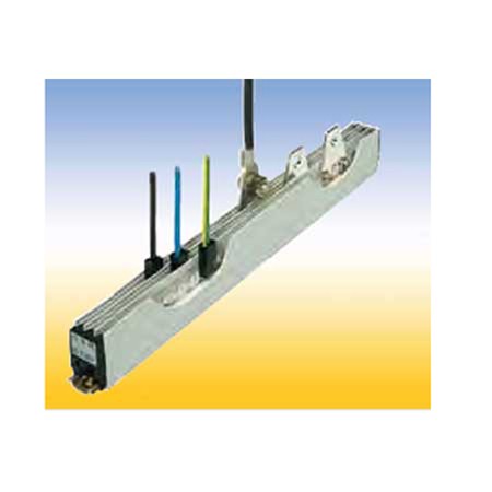
 SE Bus Bars • High current capacity up to 120 A • Two connection types • 2 or 3 pole
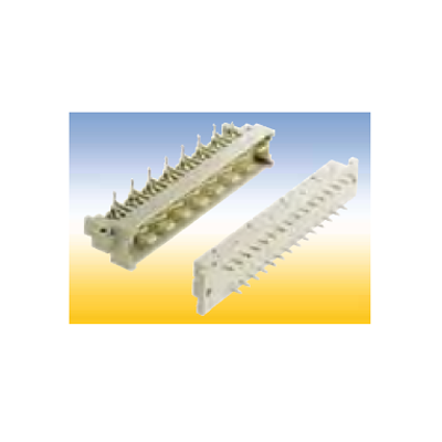 Connectors style H
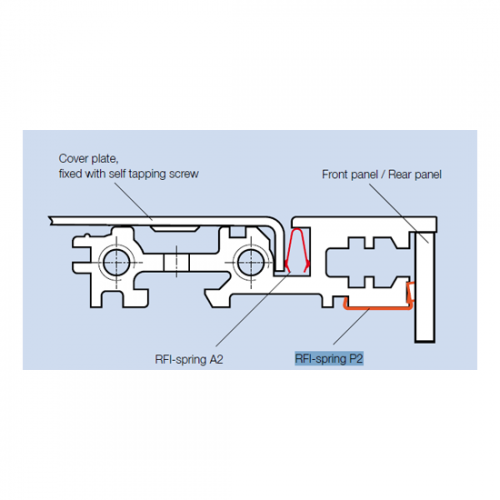 RFI-spring P2 - 84 (profile/front panel)
 Insulating Strip For insulated mounting of wiring supports, e. g. of the mounting rail B. Mounted between horizontal rail and wiring support.
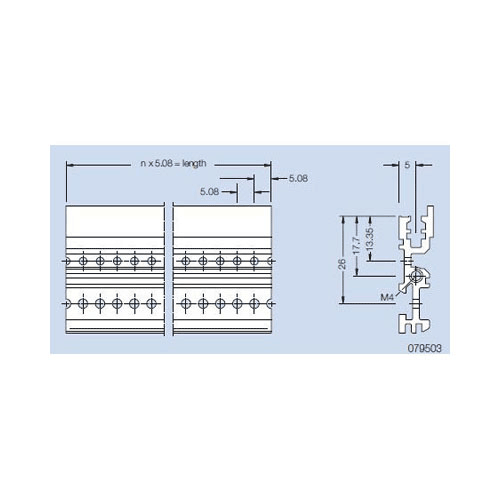 Front Profile VE1 (also rear profile by using of a front panel on the rear). Material: aluminum Finish: anodized
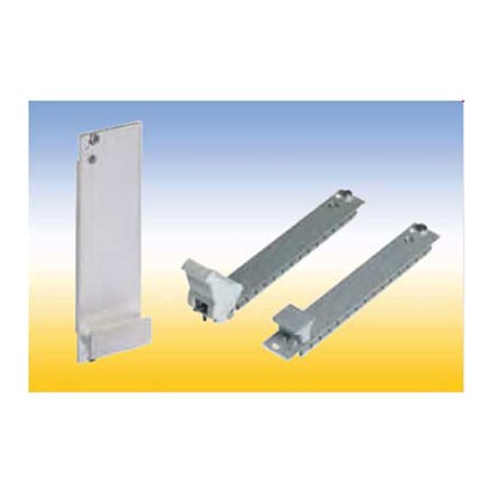
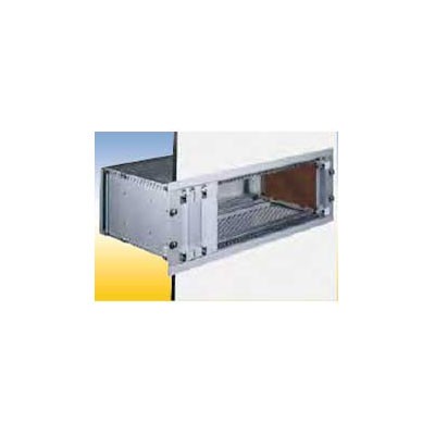 Wall and Door Installation Profile Kit For mounting subracks in a door, switch panel etc. The installation profiles are mounted to the side panel by means of the mounting screws to the horizontal rails.
- Cover Plate Fs, slide-in Hole diameter 8.5 mm. The cover plate slides in special slots in the profiles. Material: aluminum, 1.5 mm thick Finish: blank, seawater resistant
 Your advantages
- Shock and vibration resistant
- Water and dustproof
- Optimal HF-tightness
 The Subrack InterRail SNCF is a special subrack with certification from the French Railways. The system dimensions of the InterRail subrack are based on those of the FLEXIBLE Fi as a logical further development to produce a subrack for heavy-duty use. This allows unrestricted use of the extensive range of accessories.
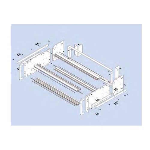 The Subrack InterRail SNCF is a special subrack with certification from the French Railways. The system dimensions of the InterRail subrack are based on those of the FLEXIBLE Fi as a logical further development to produce a subrack for heavy-duty use. This allows unrestricted use of the extensive range of accessories.
 Subrack RFI-SHIELDED IEEEdance with IEEE 1101.10. The special profile rail is designed for the use of insertion and removal handles (optionally with a hot-swap function) for overcoming high insertion and removal resistance.
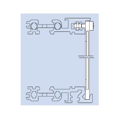 Plug-in Front Panel 85 HP The front panel bottom edge is inserted in the groove of a specially profiled rail. With slits in the side edges for insertion of RFI springs. To be used in combination with below mentioned flanges only. Finish: front side anodized, rear side conductive Delivery: 1 front panel 3 grounding bushing M 2.5 3 crosshead screw M 2.5 x 11.3
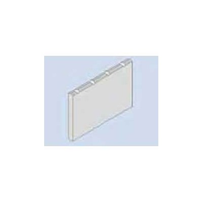 Ident-plate 4 HP The ident-plate is markable and printable. Snapped in after mounting the handle at the front panel. Material: aluminum Finish: silver silk matt anodized
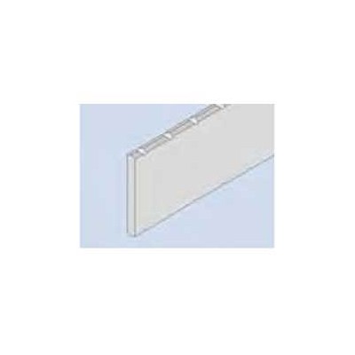 Ident Plate for handle FP. The ident plate is markable and printable, snapped in after mounting the handle to the front panel.
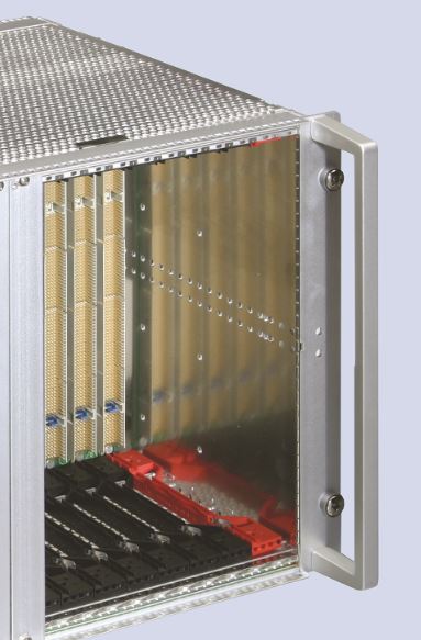
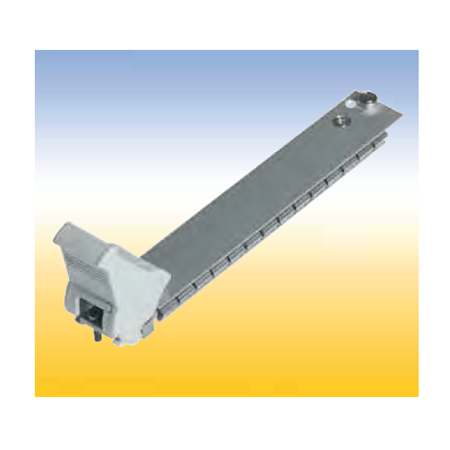
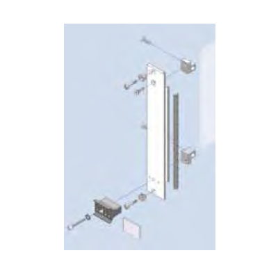
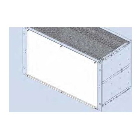 Hinged Front Panel 85 HP With slits in the side edges for insertion of RFI springs. The hinge is screwed to the profiled rail of the subrack. An 84 HP threaded strip is needed. To be used in combination with below mentioned flanges only. Finish: front side anodized, rear side conductive Delivery: 1 front panel 1 hinge 3 grounding bushings Mounting parts Delivery: as unassembled kit. Assembled kits on request.
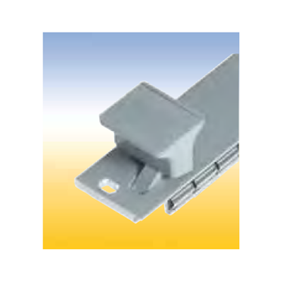
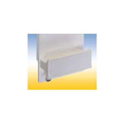 Handle FP Assembled with M 2.5 screws and with 1 additional self tapping screw from 6 HP. The handle is held against torsion by means of two nipples.
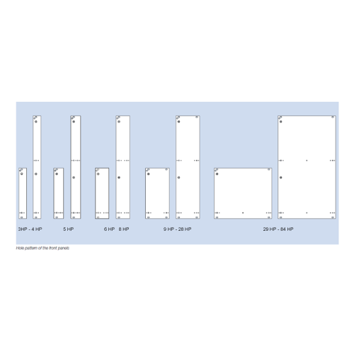 For assembly on a PCB. Handle and front connector are screwed on the front panel. The plain front panel is easy to modify. Four versions are available: 1. Flat front panel blank The front side is covered with a removable transparent foil. 2. Flat front panel anodized Front anodized, rear conductive. 3. Flat front panel RFI Front anodized, rear conductive. With slits in the side edges for insertion of RFI springs. 4. Extruded front panel RFI Made of extruded aluminum alloy, with slits in the side edges for insertion of RFI springs for contact. Surface finish is colorless chromated.
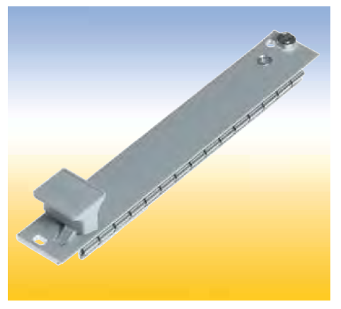
 Front Panels with Ejector Handle For easy release of PCB’s with high pin connections. The ejector handle is extends through the front panel and is screwed together with the bearing bushing at the front connector. Four versions are available: 1. Flat front panel blank. The front side is covered with a removable transparent foil. 2. Flat front panel anodized. Front anodized, rear conductive. 3. Flat front panel RFI Front anodized, rear conductive. With slits in the side edges for insertion of RFI springs. 4. Extruded front panel RFI Made of extruded aluminum alloy, with slits in the side edges for insertion of RFI springs for contact. Surface finish is colorless chromated.
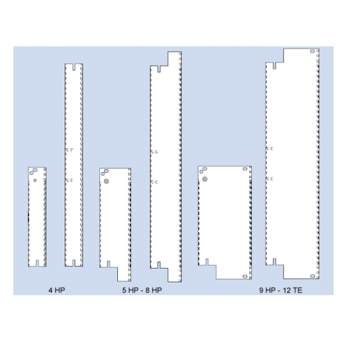 Front Panels with IEEE Handle For easy pull of PCB’s with high density connectors accordance specification IEEE 1101.10. The assambled handle kit is stuck in the milled space of the front panel and is secured with a clamped spring. Afterwards the PCB are screwed on the intergrated front connector. Two versions with IEEE handle are available: 1. Flat front panel RFI Front anodized, rear conductive. With slits in the side edges for insertion of RFI springs. 2. Extruded front panel RFI Made of extruded aluminum alloy, with slits in the side edges for insertion of RFI springs or for contacting. Surface finish is colorless chromated.
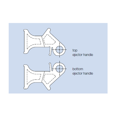 Ejector Handle The ejector handle extends through the front panel and is screwed together with the bearing bushing at the front connector.
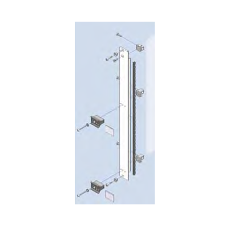 Finish: Flat front panel: front side anodized, rear side conductive Extruded front panel: colorless chromated
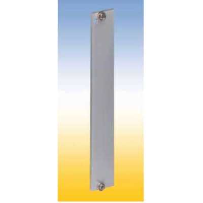 Blind Front Panels RFI Finish: flat front panel: front side anodized, rear side conductive extruded front panel: colorless chromated
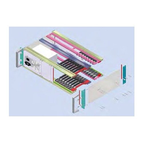 COMPACTPCI-3 U-Rear I/OI COMPACTPCI-6 U-Rear I/OI COMPACTPCI-4 U-Rear I/OI COMPACTPCI-6 +3U-Rear I/OI Consists of: 1 Subrack RFI-SHIELDED CPCI / REAR I/O 84 HP, 260 mm nom. depth (160 mm at the front, 80 mm at the rear) 1 Backplane 8 Slot, 3 U, 32 Bit, system slot right 1 ATX 300W power supply unit with a wide-range input and PFC, with assembled front panel. 1 Blind front panel 16 HP at the front. 1 Blind front panel 4 HP at the front. 1 Blind front panel 48 HP at the rear. 1 Blind front panel 8 HP at the rear. 1 Pair of card guides red 160 mm (CPU) including IEEE-coding and ESD-spring in the bottom card guide. 1 Pair of card guides red 80 mm (CPU) including IEEE-coding and ESD-spring in the bottom card guide. 7 Pair of card guides black 160 mm (CPU) including IEEE-coding and ESD-spring in the bottom card guide. 7 Pair of card guides black 80 mm (CPU) including IEEE-coding and ESD-spring in the bottom card guide
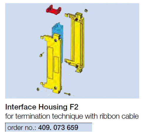
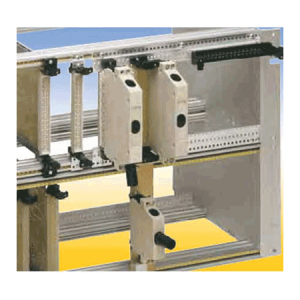
 Description This compact and insulating interface housing is designed to accommodate DIN 41 612 / IEC 60 603-2 connectors. It is physically clamped into position between guide elements. The interface housings have the following advantages:
- Accommodation of either female or male connectors of any type of connection technology.
- Protects the connector during insertion and operation.
- Lifting screws ease insertion and removal.
- Three cable feed apertures.
- Strain relief.
- Allows installation of display and operating elements.
- Codable. Metallized plastic interface housing for RFI-shielding available.

 For interface housings with female connector, to attach on the connecting pins of a U element. Installation in the wiring field of the sub rack.
 For interface housings with female connector, for mating with an I element. Installation in the wiring field of the subrack.
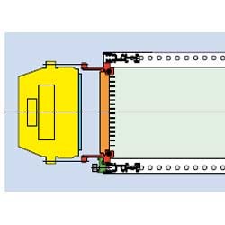
 For interface housings with female connector, for mating with a male connector, serves as a handle (GL), mounted on the service side of the subracks
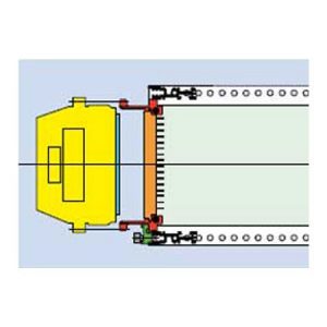 For interface housings with female connector, for mating with a male connector, serves as a handle (GL), mounted on the service side of the subracks.
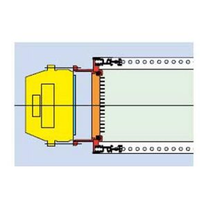 For interface housings with female connector, for mating with a male connector, serves as a handle (GL), mounted on the service side of the subracks.
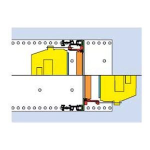 For interface housings with female connector, for mating with a male connector, on Backplane (BP).
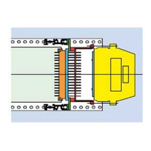 For interface housings with female connector, to attach on the connecting pins of a female connector. Installation in the wiring field of the subrack.
 For connector styles F 48, C96, H11, H15, and F24/H7.
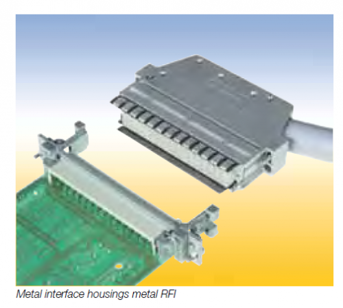 For connectors styles E 48 and E 160.
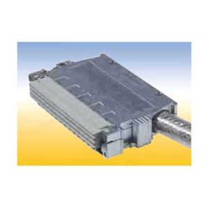 With integrated coding, for connector styles F 48, H15 and F24/H7 The Metal interface housings RFI 20 standard are not supplied with RFI springs.
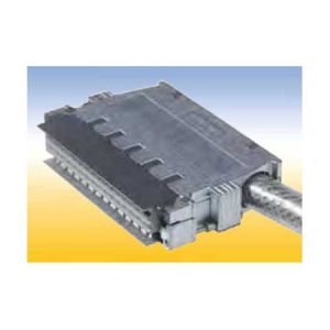 Metal Interface Housings RFI 20 COD With integrated coding, for connector styles F 48, H15 and F24/H7 width(hp) 4
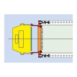 Guide component F with integrated front panel for mounting of a 3 HP metal interface housing RFI in a 3 U subrack..
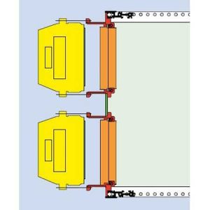 Guide component F for mounting of a 3 HP metal interface housing RFI in the upper or lower area of 6 U subracks.gers.
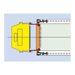 Guide component F for mounting of a 3 HP metal interface housing in any position of the mounting area.
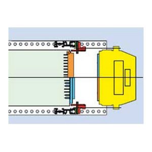 For interface housings with female or male connector, for mating di rectly to the PCB (LP) connector. Installation in the wiring field of the subrack.
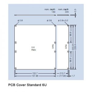
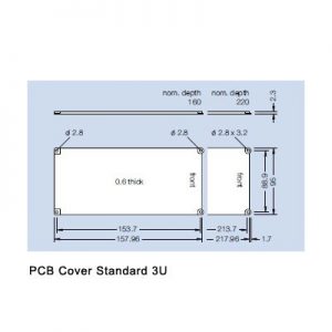
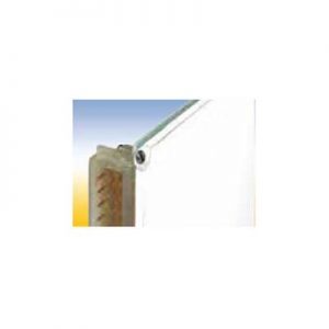 This PCB cover protect the soldered side against dirt and contact. Two versions are available: A standard PCB cover and a PCB cover for use with a coding strip. The coding strip PCB cover can be used in connection with a coding strip on the connector.
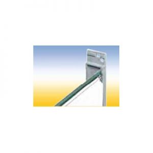 This PCB cover protect the soldered side against dirt and contact. Two versions are available: A standard PCB cover and a PCB cover for use with a coding strip. The coding strip PCB cover can be used in connection with a coding strip on the connector.
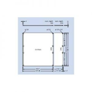
 PCB cover for coding strip 6U This PCB cover protect the soldered side against dirt and contact. Two versions are available: A standard PCB cover and a PCB cover for use with a coding strip. The coding strip PCB cover can be used in connection with a coding strip on the connector.
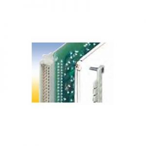 This PCB cover protect the soldered side against dirt and contact. Two versions are available: A standard PCB cover and a PCB cover for use with a coding strip. The coding strip PCB cover can be used in connection with a coding strip on the connector.
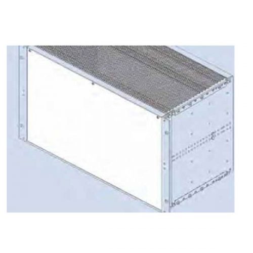
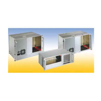
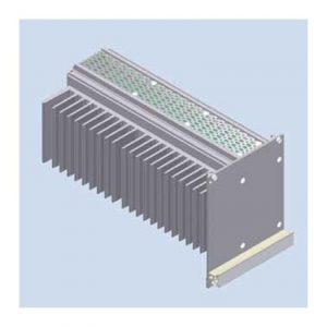 This cassette is designed for passive cooling of electronic sub assemblies and systems. The thermal power loss which is generated in the 19“ cassette is dissipated by a heat sink which also serves as sidewall. The heat sink is covered by an asymmetric front panel. Euroboards are being fitted into card guides which can be snapped in every possible position in the cassette. A wide range of accessories, for example rear cover, handle and handle strip in different colors and types are available. The front panel can be fitted with RFI springs to realize RFI shielding of the front of the subrack. Optionally the complete cassette can be RFI shielded.
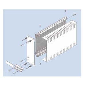 Cassette with Cover Hood Kit constists of: 1 extruded side wall 1 cover hood 1 front panel, with slits in the side edges for insertion of RFI gaskets 1 handle 1 aluminum ident plate Mounting parts
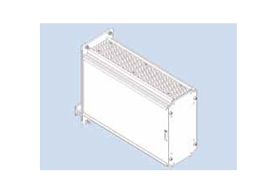
 Cassette with four Depth Profiles The cassette kits includes following rear panels: 1. Rear panel closed (RG) 2. Rear panel with partical aperture (RT) 3. Rear panel with full aperture (RV).
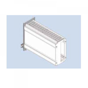 Cassette with Extruded Side Walls The cassette kits includes following rear panels: 1. Rear panel closed (RG) 2. Rear panel with partical aperture (RT) 3. Rear panel with full aperture (RV).
 Blind Front Panels RFI Finish: flat front panel: front side anodized, rear side conductive extruded front panel: colorless chromated
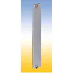 For covering empty sections or to carry various components in subracks. Four versions are available: 1. Flat front panel blank The front side is covered with a removable transparent foil. 2. Flat front panel anodized Front anodized, rear conductive. 3. Flat front panel RFI Front anodized, rear conductive, with slits in the side edges for insertion of RFI springs. 4. Extruded front panel RFI Made of extruded aluminum alloy, with slits in the side edges for insertion of RFI springs for contact. Surface finish is colorless chromated.
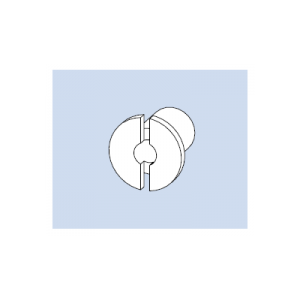 Bearing Bushing 4 for handle 4 HP Material: steel, galvanized Finish: colorless chromated Qty 50 per bag
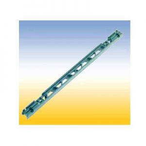
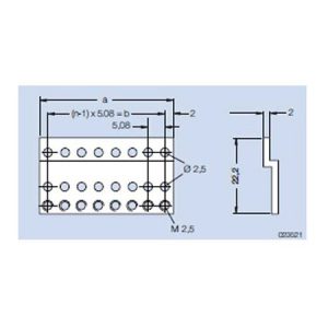 Z-Rail A tapped M 2.5 For mounting connectors in accordance to IEC 60 603/ DIN 41 612 in subracks type alpha. Mounted on the rear profile. Material: aluminum Finish: colorless chromated
 Threaded Strip M 3 addable Material: steel Finish: galvanized, chromated
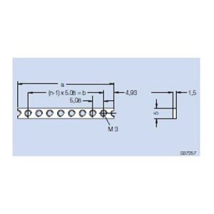 Threaded Strip M 3 Material: steel Finish: galvanized, chromated
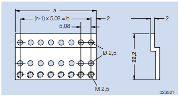
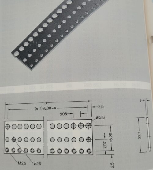
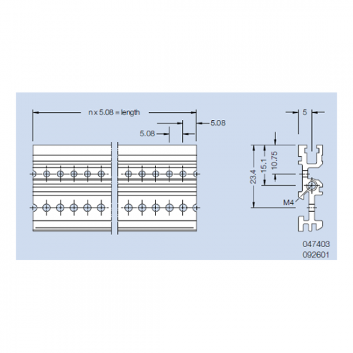
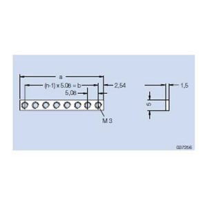 Threaded Strip M 2.5 addable This threaded strip could be added to other strips and the space between the holes always adds up 5.08 mm. Material: steel Finish: galvanized, chromated
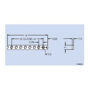 Threaded Strip M 2.5 - stainless steel For attaching the front panels and assembly parts at the wiring field. This threaded strip is for nonmagnetic applications. Material: stainless steel Finish: blank
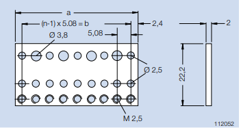
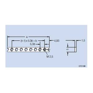 Threaded Strip M 2.5 For attaching the front panels and assembly parts at the wiring field. Material: steel Finish: galvanized, chromated
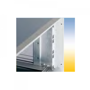
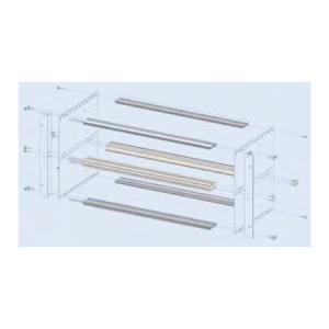 Subrack Divider Kit 2 x 3 U - 84 HP For partitioning a 6 U subrack in 2 x 3 U.
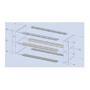 Subrack Divider Kit 2 x 3 U - 42 HP and 6 U - 40 HP The divider separates a 6 U subrack into a field for 6 U PCB’s and 2 fields of 3 U. Finish: colorless chromated Delivery: 1 double front profile 2xVE1 43 HP chromated 1 double rear profile 2xHK 43 HP anodized 2 divider strips Assembly: Mounting parts
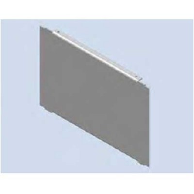 Separating Wall For separating a subrack int two fields. Material: aluminum Finish: blank Delivery: 1 separating wall Mounting parts
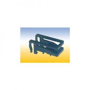 Secures PCB without front panels.
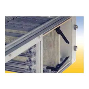 Secures PCB’s without front panels. Used for easy locking and ejecting of PCB’s
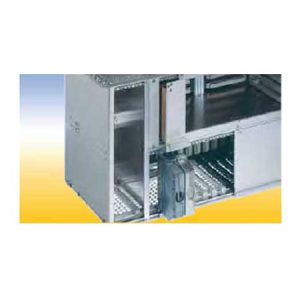 Partition Wall For partitioning of a subrack part. The partition wall 6 U can also be used as a RFI shielded subrack divider in 6 U and 2x3 U parts.
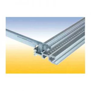
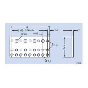 Mounting Rail B tapped M 2.5 For mounting connectors in accordance to IEC 60 603/ DIN 41 612. For mounting at the rear profile on subracks type alpha with insulating strip and insulating bushings. For mounting at the rear profile on subracks type delta. Material: aluminum Finish: blank
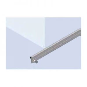 For locking of PCB‘s witout front panels. The locking rail is mounted at the horizontal rail in front of the PCB‘s. A labeling strip can be insert into a groove.
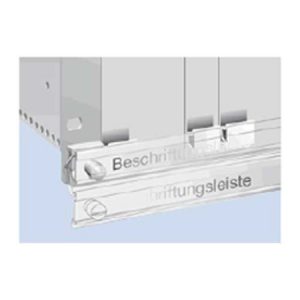 This hinged labelling rail is mounted on the subrack flanges. Normally it is placed in front of the front panels. For ejecting a PCB, the rail is turned down.
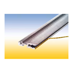 Self adhesive. For identifiying PCB slots in the subrack. The PCB slot number can be read thru the hole in the front panel. Note: The label strip cannot be read while using the RFI spring P2. Material: PC/PE foil Color: yellow/black
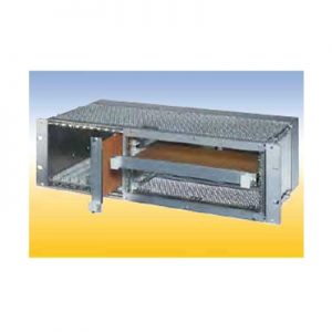 20 HP for horizontal mounting of 6 U PCB‘s in 3 U subracks. The horizontal mounting frame needs 52 HP in the width. For 84 HP subracks are available Placed right: 52 HP for horizontal mounting frame, 32 HP for 3 U PCB‘s Placed left: 52 HP for horizontal mounting frame, 1 HP for air and leakage paths, 31 HP for 3 U PCB‘s.
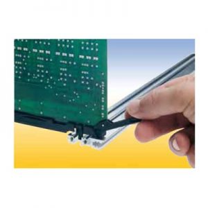
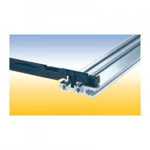 Card Guide with integrated push and pull assist This special card guide with an integral small lever aids in the handling of PCB’s with high pin plug in connectors. The lever is supported by the walls of a special guide chamber when the board is pulled out or pushed in. It is suitable for a spring to contact a track near the PCB edge. This card guides are snapin and can be secured with screws.
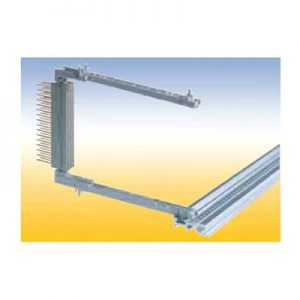 For easy screwless snap-on mounting of connectors accordance to IEC 60 603/ DIN 41 612. With a provision for a spring to contact front panels and for contacting a track near the PCB edge. This snap-in card guides can als be secured with screws.
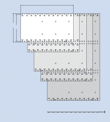
 Side Panel RFI without flange Material: aluminum, 2.5 mm thick Finish: blank, seawater resistant
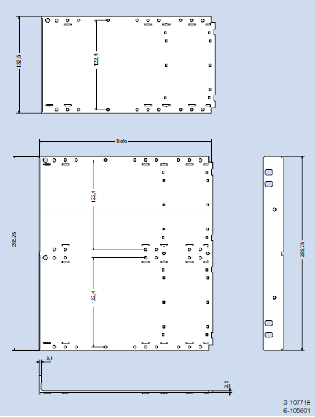
 Material: aluminum, extruded Finish: colorless chromated
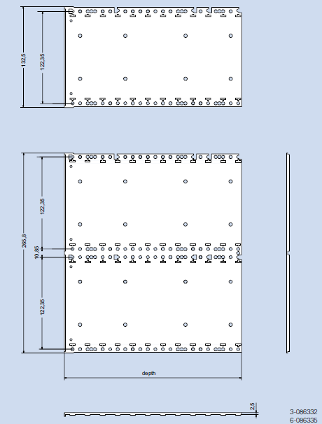
 Material: aluminum, extruded Finish: colorless chromated
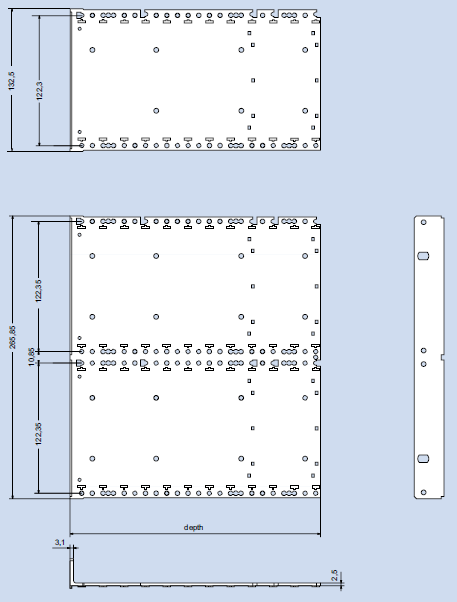
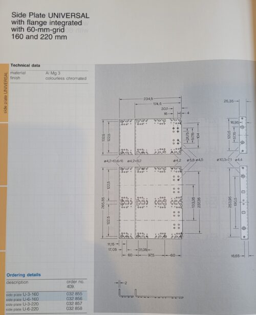
 Side Panel Fi (flange integrated) The side panel and the flange are extruded in one piece. Material: aluminum, extruded Finish: colorless anodized or colorless chromated
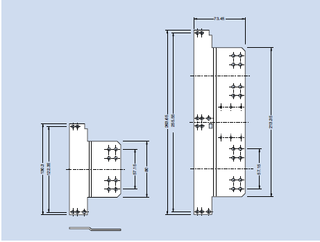
 Side Panel Extender Elongate a side panel about 60 mm to obtain a larger cabling space. The side panel extender is mounted to the side panel by means of the mounting screws for the horizontal rails. Material: aluminum, 2 mm thick Finish: colorless chromated
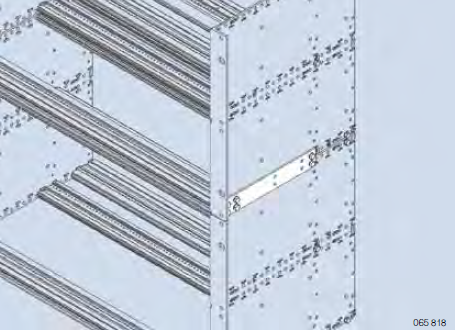
 Side Panel Connector Join two subracks, one above the other. The side panel connector is mounted to the side panels by means of the mounting screws for the horizontal rails. (nom. depth 160 mm). Material: aluminum, 2 mm thick Finish: blank
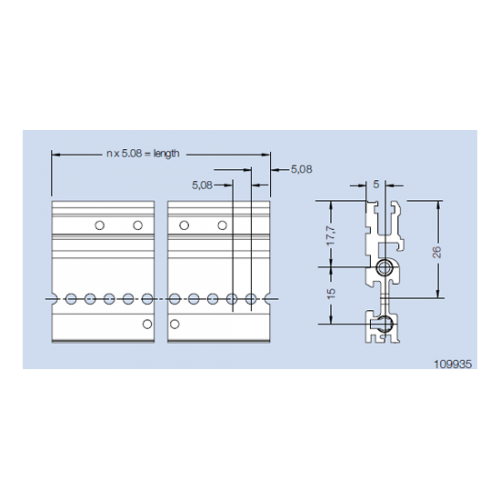 Rear Profile H22-RFI for screw on rear cover (type delta) For use with a rear cover. Material: aluminum Finish: colorless chromated
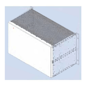 Rear Cover RFI 84 HP, inside Protective wiring rear cover for RFI shielded enclosure. Material: aluminum, 1 mm thick Finish: colorless chromated
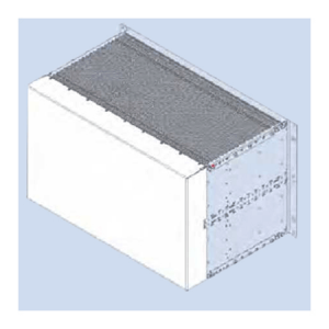 Rear Cover RFI 84 HP Protective wiring rear cover for RFI shielded enclosure. Material: aluminum, 1 mm thick Finish: colorless chromated
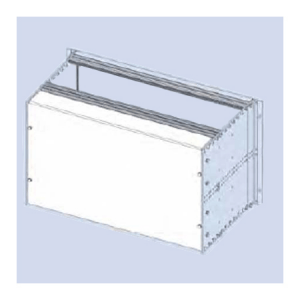 Rear Cover F 84 HP For covering the wiring field of the subrack
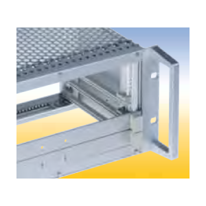 Material: aluminum Finish: anodized
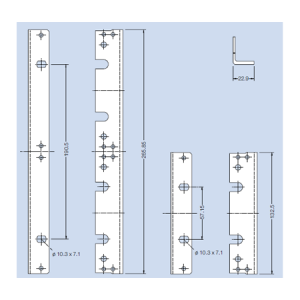 Flange without Nose This flange can be mounted at various depth on the side panel grid. Material: aluminum, extruded Finish: anodized
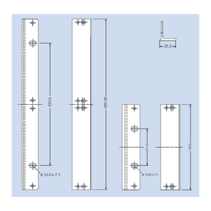 This flange is suitable for mounting of a continous front panel of 85 HP and a hinged front panel of 85 HP in a subrack. The flange will be mounted to the side panel by means of the mounting screws for the horizontal rails. Material: aluminum, extruded Finish: colorless chromated
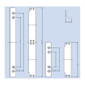 Flange for Wall Mounting For mounting of a subrack on a wall. Material: aluminum Finish: blank, seawater resistant
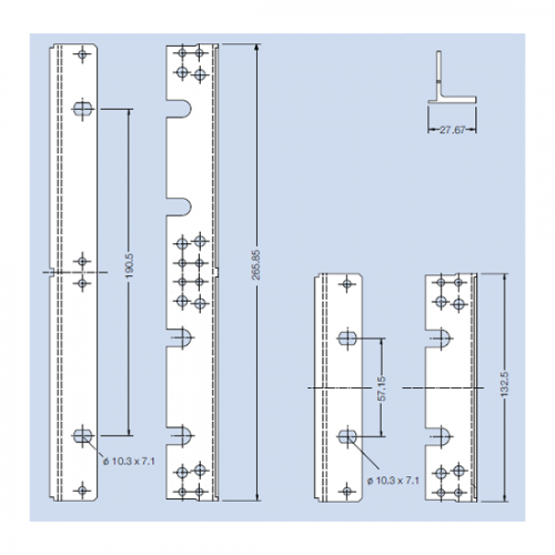 The flange can be mounted to the side panel by means of the mounting screws for the horizontal rails. Material: aluminum, extruded Finish: anodized
 Consists of: 1 Subrack RFI-SHIELDED CPCI / REAR I/O 84 HP, 260 mm nom. depth (160 mm at the front, 80 mm at the rear) 1 Backplane 8 Slot, 6 U, 64 Bit, system slot right 1 ATX 300W power supply unit with a wide-range input and PFC, with assembled front panel. (optional front panel for a drive over the power supply). 1 Blind front panel 16 HP at the front. 1 Blind front panel 4 HP at the front. 1 Blind front panel 48 HP at the rear. 1 Blind front panel 8 HP at the rear. 1 Pair of card guides red 160 mm (CPU) including IEEE-coding and ESD-spring in the bottom card guide. 1 Pair of card guides red 80 mm (CPU) including IEEE-coding and ESD-spring in the bottom card guide. 7 Pair of card guides black 160 mm (CPU) including IEEE-coding and ESD-spring in the bottom card guide. 7 Pair of card guides black 80 mm (CPU) including IEEE-coding and ESD-spring in the bottom card guide.
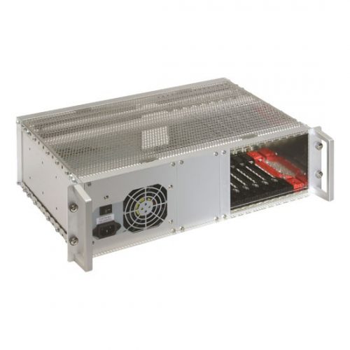 Consists of: 1 Subrack RFI-SHIELDED CPCI / REAR I/O 84 HP, 260 mm nom. depth (160 mm at the front, 80 mm at the rear) 1 Backplane 8 Slot, 3 U, 32 Bit, system slot right 1 ATX 300W power supply unit with a wide-range input and PFC, with assembled front panel. 1 Blind front panel 16 HP at the front. 1 Blind front panel 4 HP at the front. 1 Blind front panel 48 HP at the rear. 1 Blind front panel 8 HP at the rear. 1 Pair of card guides red 160 mm (CPU) including IEEE-coding and ESD-spring in the bottom card guide. 1 Pair of card guides red 160 mm (CPU) including IEEE-coding and ESD-spring in the bottom card guide. 7 Pair of card guides black 160 mm (CPU) including IEEE-coding and ESD-spring in the bottom card guide. 7 Pair of card guides black 80 mm (CPU) including IEEE-coding and ESD-spring in the bottom card guide.
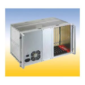 Consists of: 1 Subrack RFI-SHIELDED CPCI / REAR I/O 84 HP, 260 mm nom. depth (160 mm at the front, 80 mm at the rear) 1 Backplane 8 Slot, 6 U, 64 Bit, system slot right 1 ATX 300W power supply unit with a wide-range input and PFC, with assembled front panel. (optional front panel for a drive over the power supply). 1 Blind front panel 16 HP at the front. 1 Blind front panel 4 HP at the front. 1 Blind front panel 48 HP at the rear. 1 Blind front panel 8 HP at the rear. 1 Pair of card guides red 160 mm (CPU) including IEEE-coding and ESD-spring in the bottom card guide. 1 Pair of card guides red 80 mm (CPU) including IEEE-coding and ESD-spring in the bottom card guide. 7 Pair of card guides black 160 mm (CPU) including IEEE-coding and ESD-spring in the bottom card guide. 7 Pair of card guides black 80 mm (CPU) including IEEE-coding and ESD-spring in the bottom card guide.
 order no.: 409. 122 300 Consists of: 1 subrack RFI-SHIELDED CPCI / REAR I/O 84 HP, 260 mm nom. depth (160 mm at the front, 80 mm at the rear) for horizontal embedded 6 U PCB’s 1 Backplane 4 Slot, 6 U, 64 Bit, system slot right (1 Slot free e. g. for hard disk or driver) 2 Front panels 6 U - 4 HP (1 at the front, 1 at the rear) 1 ATX 300 W power supply unit with a wide-range input and PFC, with integrated 32 HP Front panel at the front. 1 Fan 1 Pair of card guides red 160 mm (CPU) including IEEE-coding and ESD-spring in the bottom card guide. 1 Pair of card guides red 80 mm (CPU) including IEEE-coding and ESD-spring in the bottom card guide. 4 Pair of card guides black 160 mm (CPU) including IEEE-coding and ESD-spring in the bottom card guide. 4 Pair of card guides black 80 mm (CPU) including IEEE-coding and ESD-spring in the bottom card guide
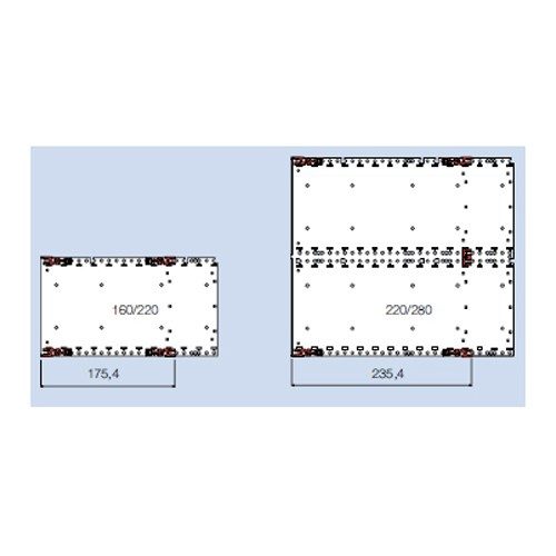 Subrack InterRail RFI The RFI-shielded version. The system dimensions of the InterRail subrack are based on those of the FLEXIBLE Fi as a logical further development to produce a subrack for heavy-duty use. This allows unrestricted use of the extensive range of accessories. The special design features of the InterRail subrack: • Profile rails with a high section modulus guarantee resistance to vibrations. • The refined RFI-shielding concept enables high shielding effectiveness (see the RFI-SHIELDED chapter).
 The system dimensions of the InterRail subrack are based on those of the FLEXIBLE Fi as a logical further development to produce a subrack for heavy-duty use. This allows unrestricted use of the extensive range of accessories. The special design features of the InterRail subrack: • Profile rails with a high section modulus guarantee resistance to vibrations. • The refined RFI-shielding concept enables high shielding effectiveness (see the RFI-SHIELDED chapter). THERE ARE FOUR VERSIONS OF THIS SUBRACK: 1. Subrack InterRail Shielding is not possible for the unsealed version. 2. Subrack InterRail RFI The RFI-shielded version. 3. Subrack InterRail RFI - IEEE The front is in accordance with IEEE 1101.10. The special profile rail is designed for the use of insertion and removal handles (optionally with a hot-swap function) for overcoming high insertion and removal resistance. The card guides are fitted with mechanical coding systems and special bonding for electrostatic discharge. 4. Subrack InterRail SNCF & InteRaiI SNCF RNI The special subrack with certification from the French Railways.
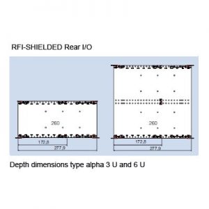 The front and the rear are in accordance with IEEE 1101.10/11. This enables insertion and removal of modules with a front panel from both the front and the rear of the subrack.
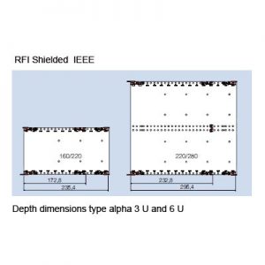 The front is in accordance with IEEE 1101.10. The special profile rail is designed for the use of insertion and removal handles (optionally with a hot-swap function) for overcoming high insertion and removal resistance.
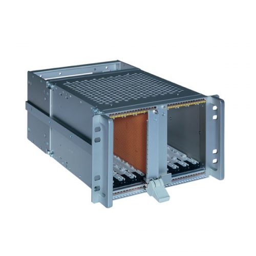
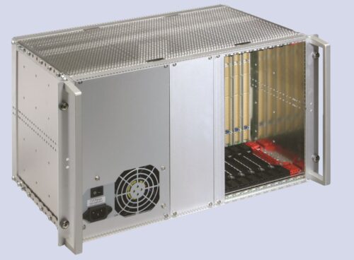
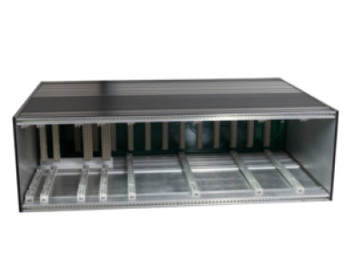
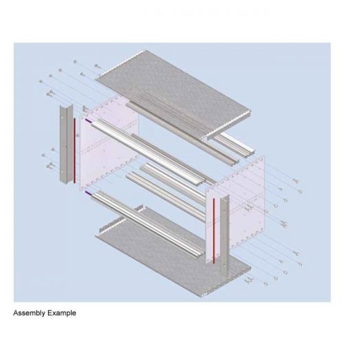 The system dimensions of the RFI- SHIELDED subrack are based on those of the FLEXIBLE subrack as a logical further development to produce the perfectly shielded subrack. This allows unrestricted use of the extensive and complete range of accessories. The special design features of the RFISHIELDED subrack: • The refined RFI shielding concept enables high shielding effectiveness. • The stable stainless steel contact springs ensure permanent and reliable bonding, even after a large number of plug-in cycles. • The perforated RFI cover plates guarantee optimal air flow for improved heat dissipation. • The use of high-quality, seawater-resistant aluminum alloys and stainless steel materials removes, for the most part, the need for unnecessary, environmentally harmful surface treatment. THERE ARE 3 VERSIONS OF THIS SUBRACK 1. Subrack RFI-SHIELDED The standard RFI-shielded version. 2. Subrack RFI-SHIELDED IEEE The front is in accordance with IEEE 1101.10. The special profile rail is designed for the use of inser tion and removal handles (optionally with a hot swap function) for overcoming high insertion and removal resistance. The card guides are fitted with mechanical coding systems and special bonding for electrostatic discharge. 3. Subrack RFI-SHIELDED IEEE / Rear I/O The front and the rear are in accordance with IEEE 1101.10/11. This enables insertion and removal of modules with a front panel from both the front and the rear of the subrack.
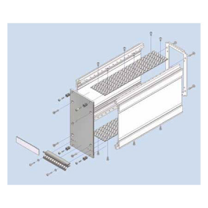
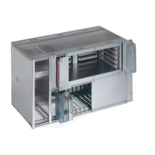
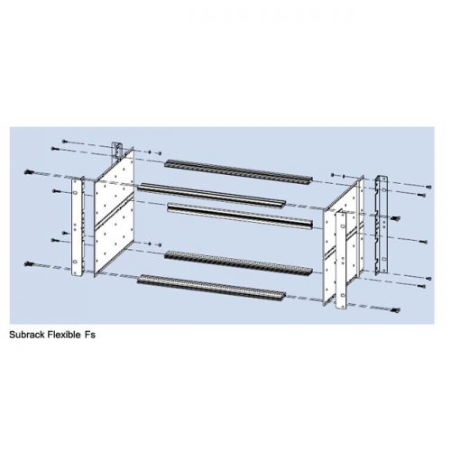
 The FLEXIBLE Fs Subrack (with a separate flange) The side wall and flange are separate components so the flange can be screwed to the side panel at the front or the rear.
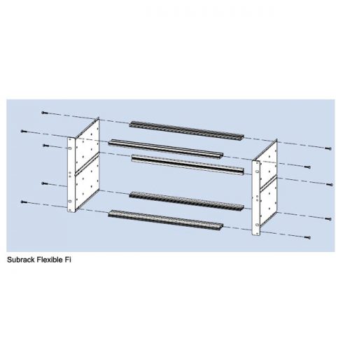 The FLEXIBLE Fi Subrack (with an integrated flange) The combination of the side wall and mounting flange form a single unit. This is the simple and cost effective version. This standard version can not be shielded.
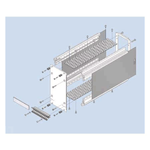
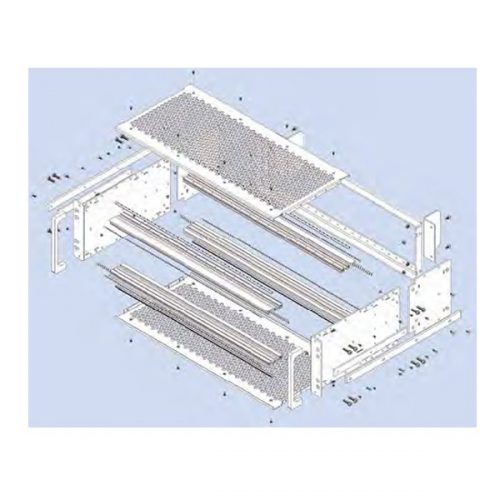
 The special design features of the subrack FLEXIBLE:
- For mounting of the profile rails the side wall is perforated with a grid of 10 mm to allow installation of modules in depth steps of 10 mm. This results in a flexible amount of free space behind the wiring level or in front of the operating level.
- The profile rails are connected to the side wall at the front using a special screw which ensures electrical bonding of the parts via a ring cutter under the head.
- The front and rear profile rails can be interchanged such that the wiring level which is normally at the rear can be implemented at the front of the subrack.
- The extensive range of accessories allows individual configuration.
- Fast and simple assembly: Easy positioning of the profile rails thanks to raised embossing on the side wall.
 Kit consists of: 2 unit supports and Installation hardware
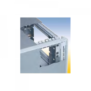 RFI-Shielding Material: stainless steel
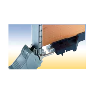 Contact Spring IEEE Snapped into the IEEE card guide or IEEE coding head to ground the alignment pin of the front panel. Material: tin-bronze order no.: 409. 113 450
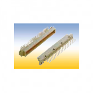 Connectors style R
 Connectors style H
 Connectors style F