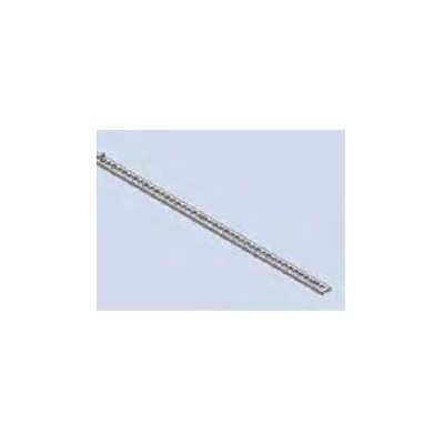
 Insulating Strip For insulated mounting of wiring supports, e. g. of the mounting rail B. Mounted between horizontal rail and wiring support.
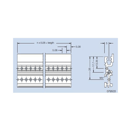
 Front Profile VE1 (also rear profile by using of a front panel on the rear). Material: aluminum Finish: anodized
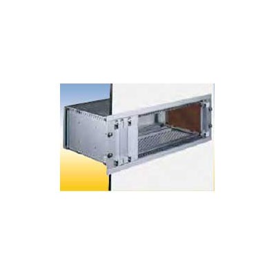
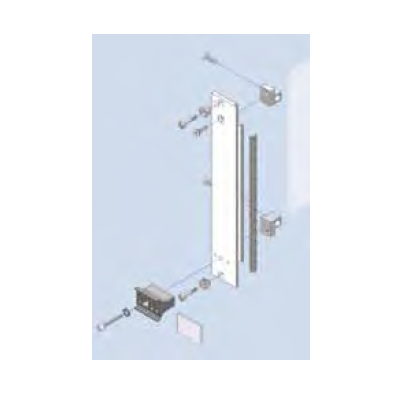
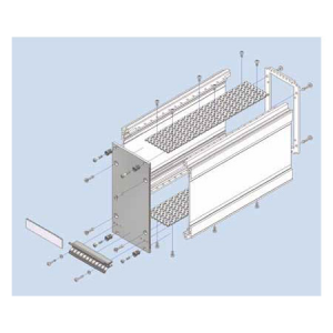
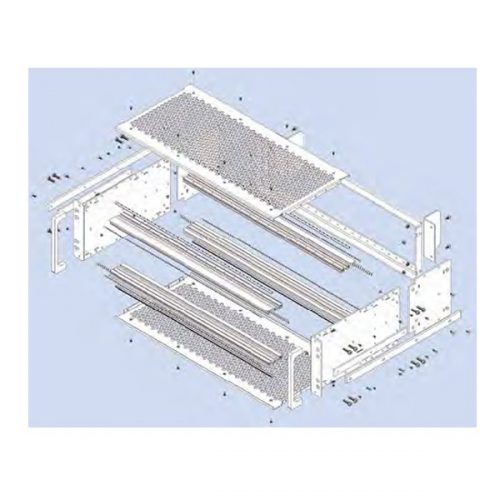
 Wall and Door Installation Profile Kit For mounting subracks in a door, switch panel etc. The installation profiles are mounted to the side panel by means of the mounting screws to the horizontal rails.
 Cover Plate Fs, slide-in Hole diameter 8.5 mm. The cover plate slides in special slots in the profiles. Material: aluminum, 1.5 mm thick Finish: blank, seawater resistant
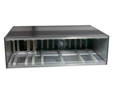
 Your advantages
- Shock and vibration resistant
- Water and dustproof
- Optimal HF-tightness
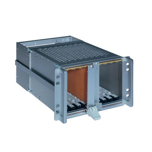
 The Subrack InterRail SNCF is a special subrack with certification from the French Railways. The system dimensions of the InterRail subrack are based on those of the FLEXIBLE Fi as a logical further development to produce a subrack for heavy-duty use. This allows unrestricted use of the extensive range of accessories.
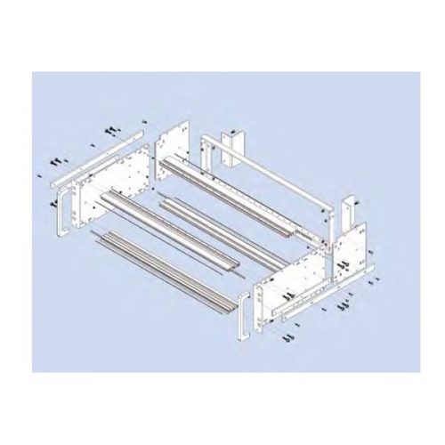 The Subrack InterRail SNCF is a special subrack with certification from the French Railways. The system dimensions of the InterRail subrack are based on those of the FLEXIBLE Fi as a logical further development to produce a subrack for heavy-duty use. This allows unrestricted use of the extensive range of accessories.
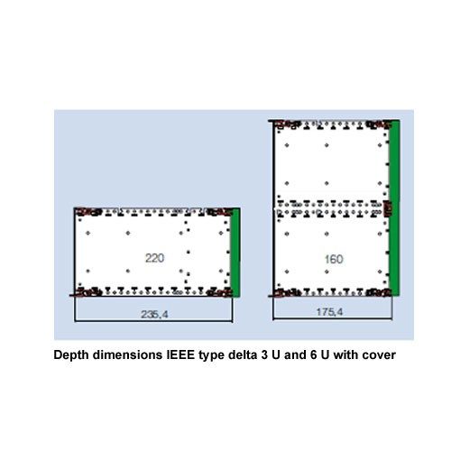 Subrack RFI-SHIELDED IEEEdance with IEEE 1101.10. The special profile rail is designed for the use of insertion and removal handles (optionally with a hot-swap function) for overcoming high insertion and removal resistance.
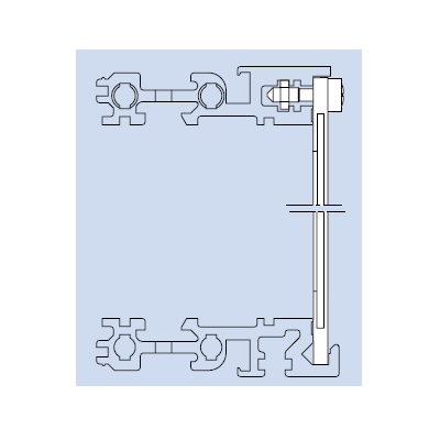 Plug-in Front Panel 85 HP The front panel bottom edge is inserted in the groove of a specially profiled rail. With slits in the side edges for insertion of RFI springs. To be used in combination with below mentioned flanges only. Finish: front side anodized, rear side conductive Delivery: 1 front panel 3 grounding bushing M 2.5 3 crosshead screw M 2.5 x 11.3
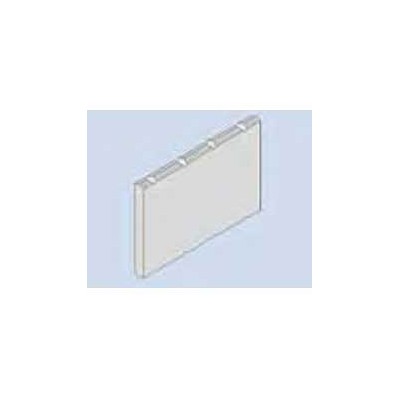 Ident-plate 4 HP The ident-plate is markable and printable. Snapped in after mounting the handle at the front panel. Material: aluminum Finish: silver silk matt anodized
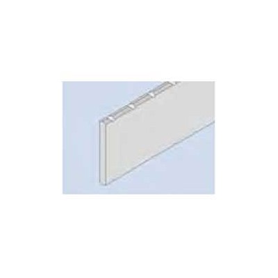 Ident Plate for handle FP. The ident plate is markable and printable, snapped in after mounting the handle to the front panel.
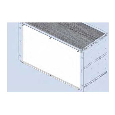
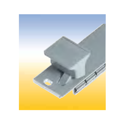
 Hinged Front Panel 85 HP With slits in the side edges for insertion of RFI springs. The hinge is screwed to the profiled rail of the subrack. An 84 HP threaded strip is needed. To be used in combination with below mentioned flanges only. Finish: front side anodized, rear side conductive Delivery: 1 front panel 1 hinge 3 grounding bushings Mounting parts Delivery: as unassembled kit. Assembled kits on request.
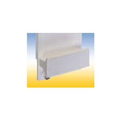 Handle FP Assembled with M 2.5 screws and with 1 additional self tapping screw from 6 HP. The handle is held against torsion by means of two nipples.
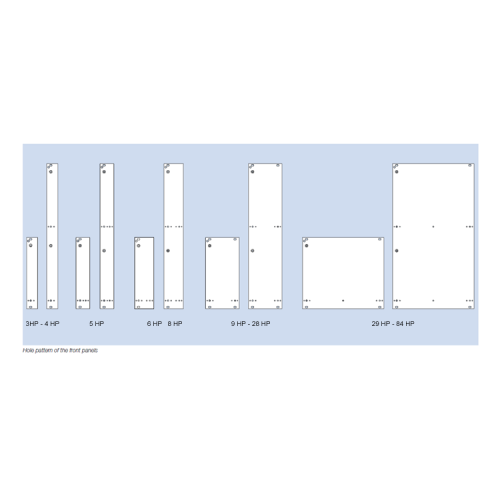 For assembly on a PCB. Handle and front connector are screwed on the front panel. The plain front panel is easy to modify. Four versions are available: 1. Flat front panel blank The front side is covered with a removable transparent foil. 2. Flat front panel anodized Front anodized, rear conductive. 3. Flat front panel RFI Front anodized, rear conductive. With slits in the side edges for insertion of RFI springs. 4. Extruded front panel RFI Made of extruded aluminum alloy, with slits in the side edges for insertion of RFI springs for contact. Surface finish is colorless chromated.
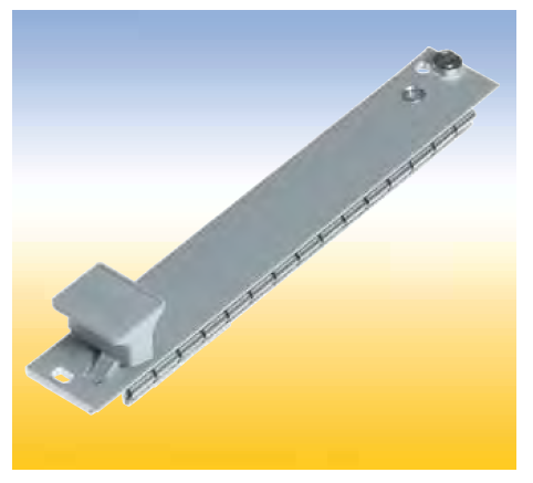
 Front Panels with Ejector Handle For easy release of PCB’s with high pin connections. The ejector handle is extends through the front panel and is screwed together with the bearing bushing at the front connector. Four versions are available: 1. Flat front panel blank. The front side is covered with a removable transparent foil. 2. Flat front panel anodized. Front anodized, rear conductive. 3. Flat front panel RFI Front anodized, rear conductive. With slits in the side edges for insertion of RFI springs. 4. Extruded front panel RFI Made of extruded aluminum alloy, with slits in the side edges for insertion of RFI springs for contact. Surface finish is colorless chromated.
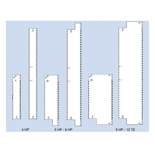 Front Panels with IEEE Handle For easy pull of PCB’s with high density connectors accordance specification IEEE 1101.10. The assambled handle kit is stuck in the milled space of the front panel and is secured with a clamped spring. Afterwards the PCB are screwed on the intergrated front connector. Two versions with IEEE handle are available: 1. Flat front panel RFI Front anodized, rear conductive. With slits in the side edges for insertion of RFI springs. 2. Extruded front panel RFI Made of extruded aluminum alloy, with slits in the side edges for insertion of RFI springs or for contacting. Surface finish is colorless chromated.
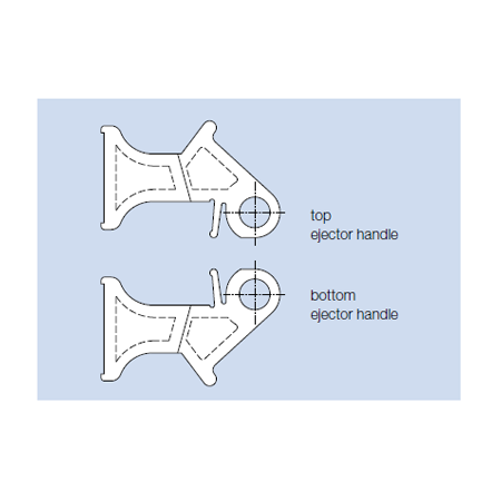 Ejector Handle The ejector handle extends through the front panel and is screwed together with the bearing bushing at the front connector.
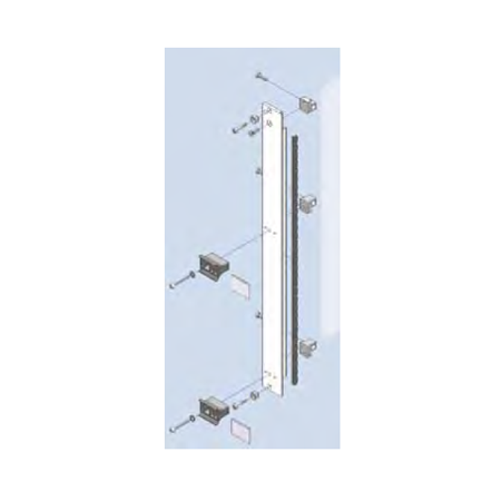 Finish: Flat front panel: front side anodized, rear side conductive Extruded front panel: colorless chromated
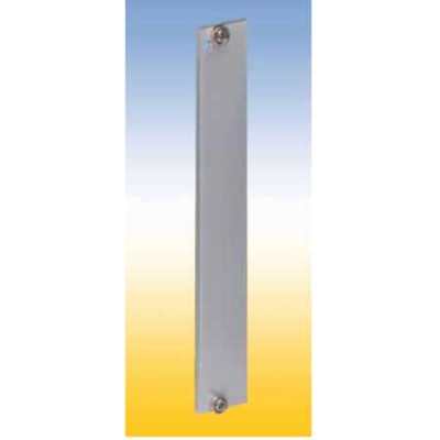 Blind Front Panels RFI Finish: flat front panel: front side anodized, rear side conductive extruded front panel: colorless chromated
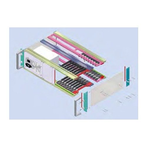 COMPACTPCI-3 U-Rear I/OI COMPACTPCI-6 U-Rear I/OI COMPACTPCI-4 U-Rear I/OI COMPACTPCI-6 +3U-Rear I/OI Consists of: 1 Subrack RFI-SHIELDED CPCI / REAR I/O 84 HP, 260 mm nom. depth (160 mm at the front, 80 mm at the rear) 1 Backplane 8 Slot, 3 U, 32 Bit, system slot right 1 ATX 300W power supply unit with a wide-range input and PFC, with assembled front panel. 1 Blind front panel 16 HP at the front. 1 Blind front panel 4 HP at the front. 1 Blind front panel 48 HP at the rear. 1 Blind front panel 8 HP at the rear. 1 Pair of card guides red 160 mm (CPU) including IEEE-coding and ESD-spring in the bottom card guide. 1 Pair of card guides red 80 mm (CPU) including IEEE-coding and ESD-spring in the bottom card guide. 7 Pair of card guides black 160 mm (CPU) including IEEE-coding and ESD-spring in the bottom card guide. 7 Pair of card guides black 80 mm (CPU) including IEEE-coding and ESD-spring in the bottom card guide
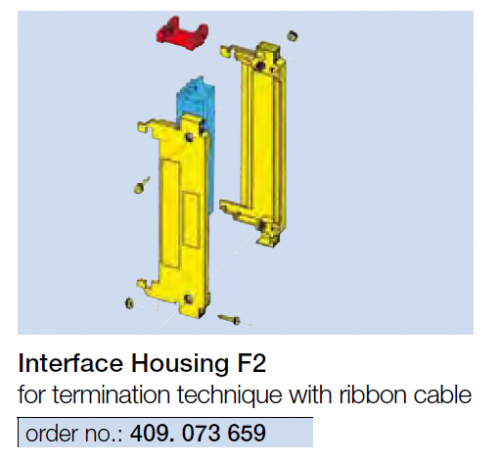

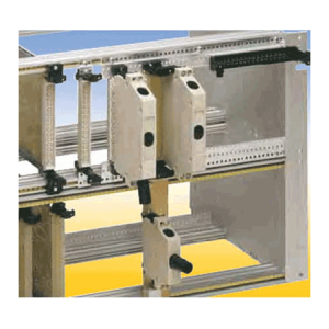
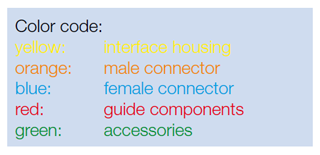
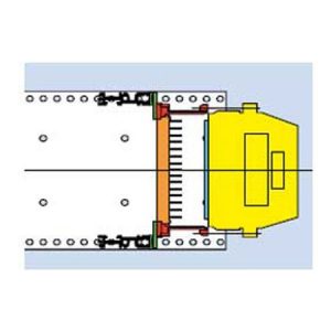
 Description This compact and insulating interface housing is designed to accommodate DIN 41 612 / IEC 60 603-2 connectors. It is physically clamped into position between guide elements. The interface housings have the following advantages:
- Accommodation of either female or male connectors of any type of connection technology.
- Protects the connector during insertion and operation.
- Lifting screws ease insertion and removal.
- Three cable feed apertures.
- Strain relief.
- Allows installation of display and operating elements.
- Codable. Metallized plastic interface housing for RFI-shielding available.

 For interface housings with female connector, to attach on the connecting pins of a U element. Installation in the wiring field of the sub rack.
 For interface housings with female connector, for mating with an I element. Installation in the wiring field of the subrack.
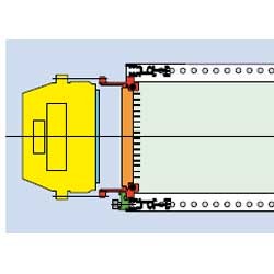
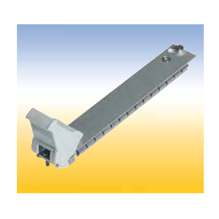
 For interface housings with female connector, for mating with a male connector, serves as a handle (GL), mounted on the service side of the subracks
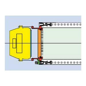 For interface housings with female connector, for mating with a male connector, serves as a handle (GL), mounted on the service side of the subracks.
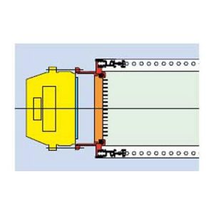 For interface housings with female connector, for mating with a male connector, serves as a handle (GL), mounted on the service side of the subracks.
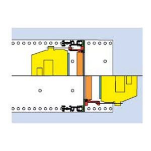 For interface housings with female connector, for mating with a male connector, on Backplane (BP).
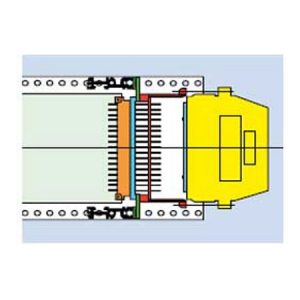 For interface housings with female connector, to attach on the connecting pins of a female connector. Installation in the wiring field of the subrack.
 For connector styles F 48, C96, H11, H15, and F24/H7.
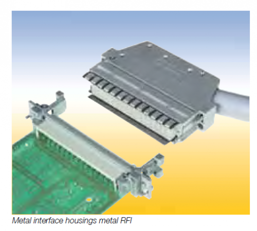 For connectors styles E 48 and E 160.
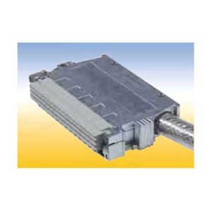 With integrated coding, for connector styles F 48, H15 and F24/H7 The Metal interface housings RFI 20 standard are not supplied with RFI springs.
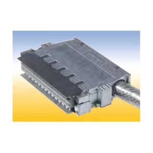 Metal Interface Housings RFI 20 COD With integrated coding, for connector styles F 48, H15 and F24/H7 width(hp) 4
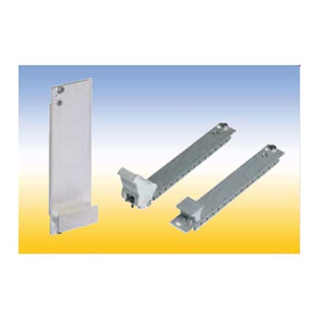
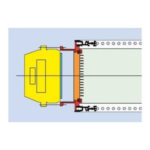 Guide component F with integrated front panel for mounting of a 3 HP metal interface housing RFI in a 3 U subrack..
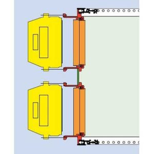 Guide component F for mounting of a 3 HP metal interface housing RFI in the upper or lower area of 6 U subracks.gers.
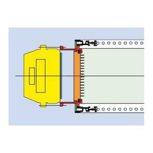 Guide component F for mounting of a 3 HP metal interface housing in any position of the mounting area.
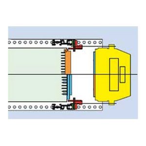 For interface housings with female or male connector, for mating di rectly to the PCB (LP) connector. Installation in the wiring field of the subrack.
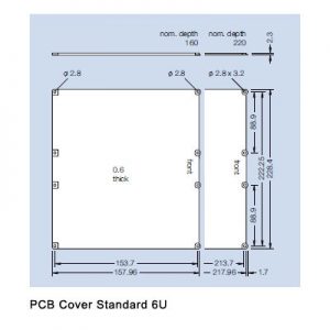
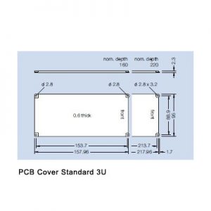
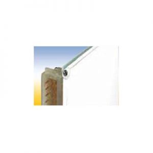 This PCB cover protect the soldered side against dirt and contact. Two versions are available: A standard PCB cover and a PCB cover for use with a coding strip. The coding strip PCB cover can be used in connection with a coding strip on the connector.
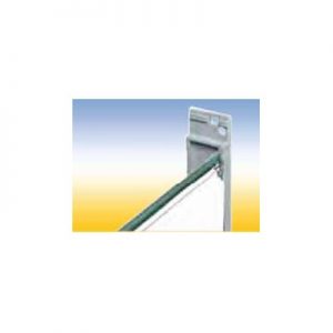 This PCB cover protect the soldered side against dirt and contact. Two versions are available: A standard PCB cover and a PCB cover for use with a coding strip. The coding strip PCB cover can be used in connection with a coding strip on the connector.
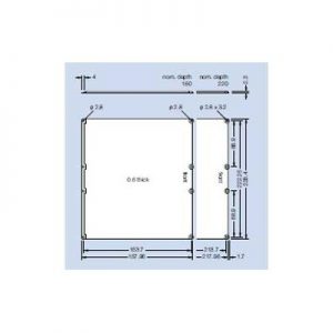
 PCB cover for coding strip 6U This PCB cover protect the soldered side against dirt and contact. Two versions are available: A standard PCB cover and a PCB cover for use with a coding strip. The coding strip PCB cover can be used in connection with a coding strip on the connector.
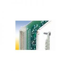 This PCB cover protect the soldered side against dirt and contact. Two versions are available: A standard PCB cover and a PCB cover for use with a coding strip. The coding strip PCB cover can be used in connection with a coding strip on the connector.
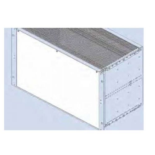
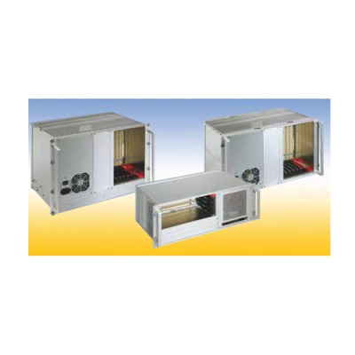
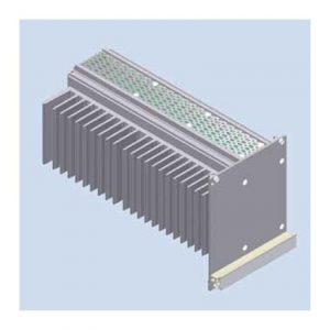 This cassette is designed for passive cooling of electronic sub assemblies and systems. The thermal power loss which is generated in the 19“ cassette is dissipated by a heat sink which also serves as sidewall. The heat sink is covered by an asymmetric front panel. Euroboards are being fitted into card guides which can be snapped in every possible position in the cassette. A wide range of accessories, for example rear cover, handle and handle strip in different colors and types are available. The front panel can be fitted with RFI springs to realize RFI shielding of the front of the subrack. Optionally the complete cassette can be RFI shielded.
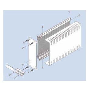 Cassette with Cover Hood Kit constists of: 1 extruded side wall 1 cover hood 1 front panel, with slits in the side edges for insertion of RFI gaskets 1 handle 1 aluminum ident plate Mounting parts
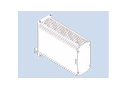
 Cassette with four Depth Profiles The cassette kits includes following rear panels: 1. Rear panel closed (RG) 2. Rear panel with partical aperture (RT) 3. Rear panel with full aperture (RV).
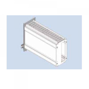 Cassette with Extruded Side Walls The cassette kits includes following rear panels: 1. Rear panel closed (RG) 2. Rear panel with partical aperture (RT) 3. Rear panel with full aperture (RV).
 Blind Front Panels RFI Finish: flat front panel: front side anodized, rear side conductive extruded front panel: colorless chromated
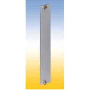 For covering empty sections or to carry various components in subracks. Four versions are available: 1. Flat front panel blank The front side is covered with a removable transparent foil. 2. Flat front panel anodized Front anodized, rear conductive. 3. Flat front panel RFI Front anodized, rear conductive, with slits in the side edges for insertion of RFI springs. 4. Extruded front panel RFI Made of extruded aluminum alloy, with slits in the side edges for insertion of RFI springs for contact. Surface finish is colorless chromated.
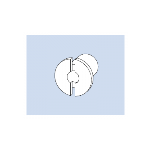 Bearing Bushing 4 for handle 4 HP Material: steel, galvanized Finish: colorless chromated Qty 50 per bag
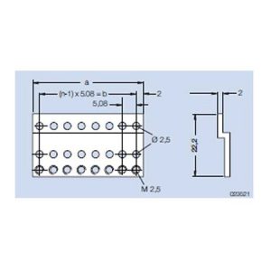 Z-Rail A tapped M 2.5 For mounting connectors in accordance to IEC 60 603/ DIN 41 612 in subracks type alpha. Mounted on the rear profile. Material: aluminum Finish: colorless chromated
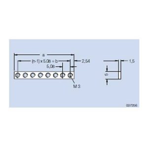 Threaded Strip M 3 addable Material: steel Finish: galvanized, chromated
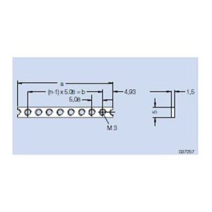 Threaded Strip M 3 Material: steel Finish: galvanized, chromated