 Rear Cover RFI 84 HP, inside Protective wiring rear cover for RFI shielded enclosure. Material: aluminum, 1 mm thick Finish: colorless chromated
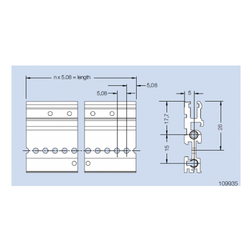
 Rear Profile H22-RFI for screw on rear cover (type delta) For use with a rear cover. Material: aluminum Finish: colorless chromated
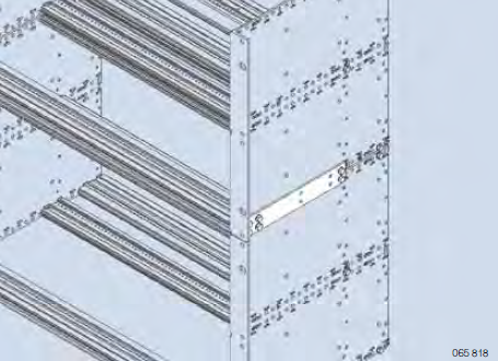
 Side Panel Connector Join two subracks, one above the other. The side panel connector is mounted to the side panels by means of the mounting screws for the horizontal rails. (nom. depth 160 mm). Material: aluminum, 2 mm thick Finish: blank
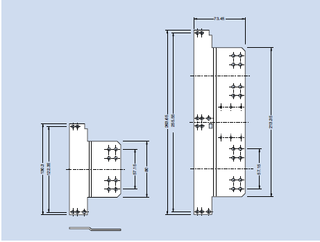
 Side Panel Extender Elongate a side panel about 60 mm to obtain a larger cabling space. The side panel extender is mounted to the side panel by means of the mounting screws for the horizontal rails. Material: aluminum, 2 mm thick Finish: colorless chromated
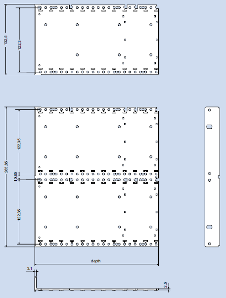
 Side Panel Fi (flange integrated) The side panel and the flange are extruded in one piece. Material: aluminum, extruded Finish: colorless anodized or colorless chromated
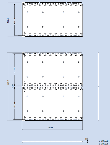
 Material: aluminum, extruded Finish: colorless chromated
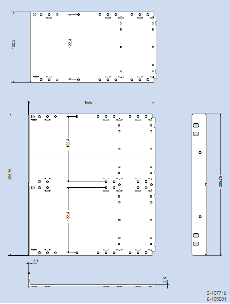
 Material: aluminum, extruded Finish: colorless chromated
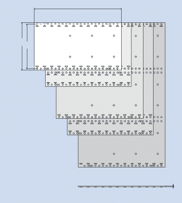
 Side Panel RFI without flange Material: aluminum, 2.5 mm thick Finish: blank, seawater resistant
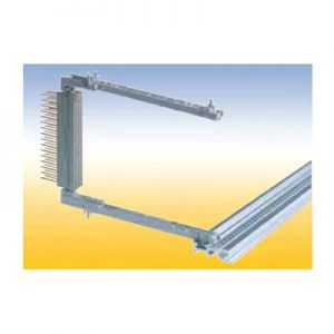
 For easy screwless snap-on mounting of connectors accordance to IEC 60 603/ DIN 41 612. With a provision for a spring to contact front panels and for contacting a track near the PCB edge. This snap-in card guides can als be secured with screws.
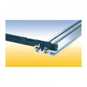 Card Guide with integrated push and pull assist This special card guide with an integral small lever aids in the handling of PCB’s with high pin plug in connectors. The lever is supported by the walls of a special guide chamber when the board is pulled out or pushed in. It is suitable for a spring to contact a track near the PCB edge. This card guides are snapin and can be secured with screws.
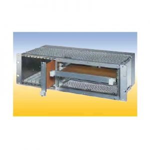 20 HP for horizontal mounting of 6 U PCB‘s in 3 U subracks. The horizontal mounting frame needs 52 HP in the width. For 84 HP subracks are available Placed right: 52 HP for horizontal mounting frame, 32 HP for 3 U PCB‘s Placed left: 52 HP for horizontal mounting frame, 1 HP for air and leakage paths, 31 HP for 3 U PCB‘s.
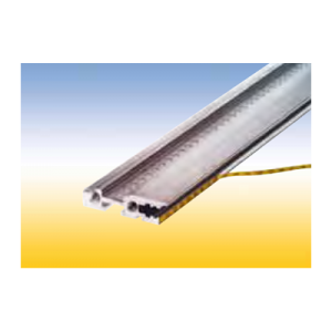 Self adhesive. For identifiying PCB slots in the subrack. The PCB slot number can be read thru the hole in the front panel. Note: The label strip cannot be read while using the RFI spring P2. Material: PC/PE foil Color: yellow/black
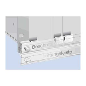 This hinged labelling rail is mounted on the subrack flanges. Normally it is placed in front of the front panels. For ejecting a PCB, the rail is turned down.
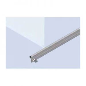 For locking of PCB‘s witout front panels. The locking rail is mounted at the horizontal rail in front of the PCB‘s. A labeling strip can be insert into a groove.
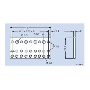 Mounting Rail B tapped M 2.5 For mounting connectors in accordance to IEC 60 603/ DIN 41 612. For mounting at the rear profile on subracks type alpha with insulating strip and insulating bushings. For mounting at the rear profile on subracks type delta. Material: aluminum Finish: blank
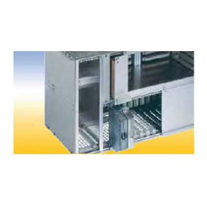 Partition Wall For partitioning of a subrack part. The partition wall 6 U can also be used as a RFI shielded subrack divider in 6 U and 2x3 U parts.
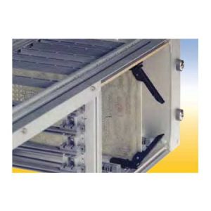 Secures PCB’s without front panels. Used for easy locking and ejecting of PCB’s
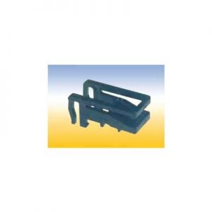 Secures PCB without front panels.
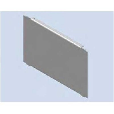
 Separating Wall For separating a subrack int two fields. Material: aluminum Finish: blank Delivery: 1 separating wall Mounting parts
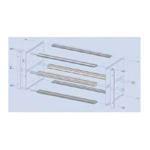 Subrack Divider Kit 2 x 3 U - 42 HP and 6 U - 40 HP The divider separates a 6 U subrack into a field for 6 U PCB’s and 2 fields of 3 U. Finish: colorless chromated Delivery: 1 double front profile 2xVE1 43 HP chromated 1 double rear profile 2xHK 43 HP anodized 2 divider strips Assembly: Mounting parts
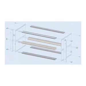 Subrack Divider Kit 2 x 3 U - 84 HP For partitioning a 6 U subrack in 2 x 3 U.
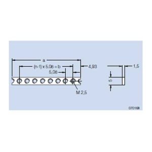 Threaded Strip M 2.5 For attaching the front panels and assembly parts at the wiring field. Material: steel Finish: galvanized, chromated
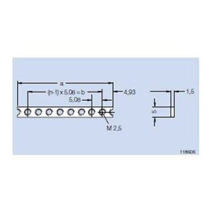 Threaded Strip M 2.5 - stainless steel For attaching the front panels and assembly parts at the wiring field. This threaded strip is for nonmagnetic applications. Material: stainless steel Finish: blank
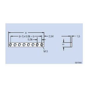 Threaded Strip M 2.5 addable This threaded strip could be added to other strips and the space between the holes always adds up 5.08 mm. Material: steel Finish: galvanized, chromated
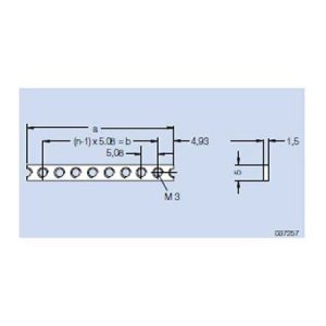 Threaded Strip M 3 Material: steel Finish: galvanized, chromated
 Threaded Strip M 3 addable Material: steel Finish: galvanized, chromated
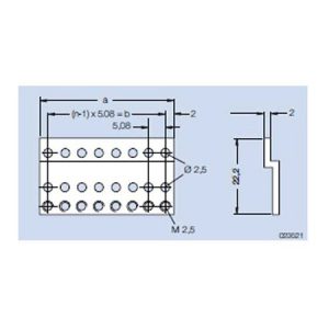 Z-Rail A tapped M 2.5 For mounting connectors in accordance to IEC 60 603/ DIN 41 612 in subracks type alpha. Mounted on the rear profile. Material: aluminum Finish: colorless chromated
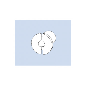 Bearing Bushing 4 for handle 4 HP Material: steel, galvanized Finish: colorless chromated Qty 50 per bag
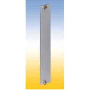 For covering empty sections or to carry various components in subracks. Four versions are available: 1. Flat front panel blank The front side is covered with a removable transparent foil. 2. Flat front panel anodized Front anodized, rear conductive. 3. Flat front panel RFI Front anodized, rear conductive, with slits in the side edges for insertion of RFI springs. 4. Extruded front panel RFI Made of extruded aluminum alloy, with slits in the side edges for insertion of RFI springs for contact. Surface finish is colorless chromated.
 Blind Front Panels RFI Finish: flat front panel: front side anodized, rear side conductive extruded front panel: colorless chromated
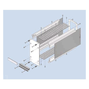
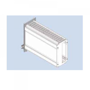 Cassette with Extruded Side Walls The cassette kits includes following rear panels: 1. Rear panel closed (RG) 2. Rear panel with partical aperture (RT) 3. Rear panel with full aperture (RV).
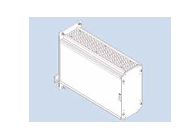
 Cassette with four Depth Profiles The cassette kits includes following rear panels: 1. Rear panel closed (RG) 2. Rear panel with partical aperture (RT) 3. Rear panel with full aperture (RV).
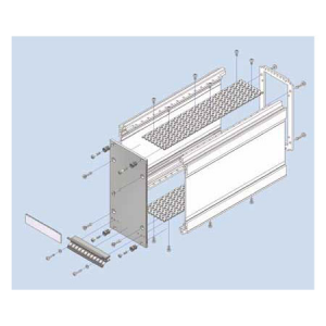
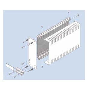 Cassette with Cover Hood Kit constists of: 1 extruded side wall 1 cover hood 1 front panel, with slits in the side edges for insertion of RFI gaskets 1 handle 1 aluminum ident plate Mounting parts
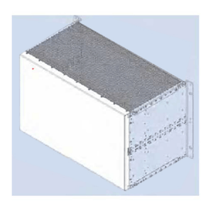
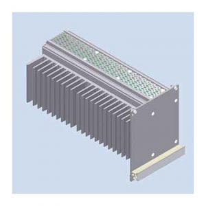 This cassette is designed for passive cooling of electronic sub assemblies and systems. The thermal power loss which is generated in the 19“ cassette is dissipated by a heat sink which also serves as sidewall. The heat sink is covered by an asymmetric front panel. Euroboards are being fitted into card guides which can be snapped in every possible position in the cassette. A wide range of accessories, for example rear cover, handle and handle strip in different colors and types are available. The front panel can be fitted with RFI springs to realize RFI shielding of the front of the subrack. Optionally the complete cassette can be RFI shielded.
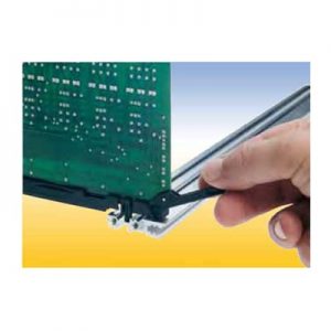
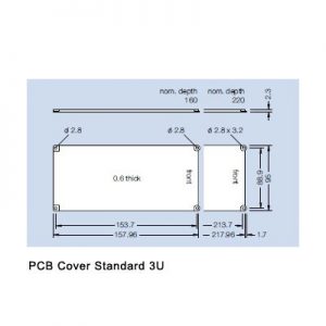
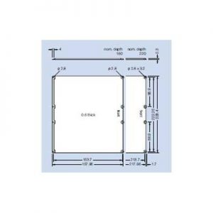
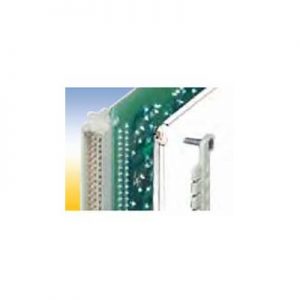 This PCB cover protect the soldered side against dirt and contact. Two versions are available: A standard PCB cover and a PCB cover for use with a coding strip. The coding strip PCB cover can be used in connection with a coding strip on the connector.
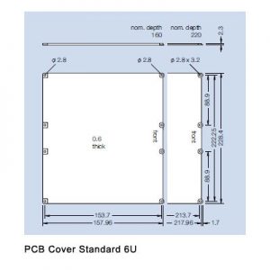
 PCB cover for coding strip 6U This PCB cover protect the soldered side against dirt and contact. Two versions are available: A standard PCB cover and a PCB cover for use with a coding strip. The coding strip PCB cover can be used in connection with a coding strip on the connector.
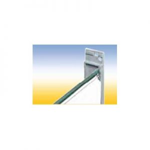 This PCB cover protect the soldered side against dirt and contact. Two versions are available: A standard PCB cover and a PCB cover for use with a coding strip. The coding strip PCB cover can be used in connection with a coding strip on the connector.
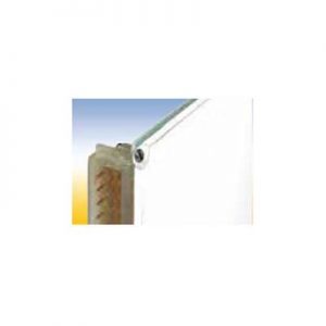 This PCB cover protect the soldered side against dirt and contact. Two versions are available: A standard PCB cover and a PCB cover for use with a coding strip. The coding strip PCB cover can be used in connection with a coding strip on the connector.
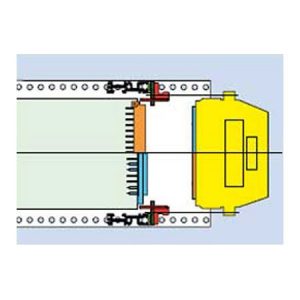 For interface housings with female or male connector, for mating di rectly to the PCB (LP) connector. Installation in the wiring field of the subrack.
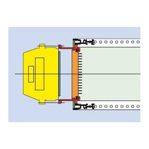 Guide component F for mounting of a 3 HP metal interface housing in any position of the mounting area.
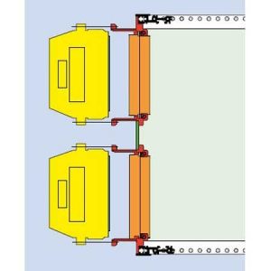 Guide component F for mounting of a 3 HP metal interface housing RFI in the upper or lower area of 6 U subracks.gers.
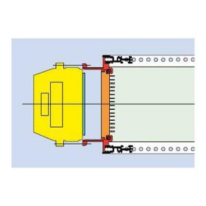 Guide component F with integrated front panel for mounting of a 3 HP metal interface housing RFI in a 3 U subrack..
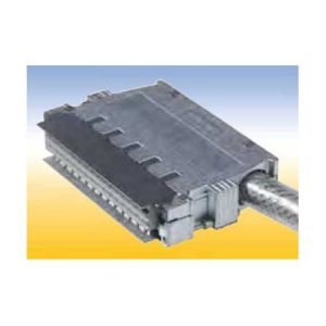 Metal Interface Housings RFI 20 COD With integrated coding, for connector styles F 48, H15 and F24/H7 width(hp) 4
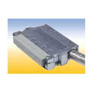 With integrated coding, for connector styles F 48, H15 and F24/H7 The Metal interface housings RFI 20 standard are not supplied with RFI springs.
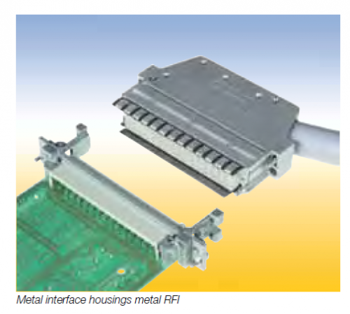
 For connectors styles E 48 and E 160.
 For connector styles F 48, C96, H11, H15, and F24/H7.
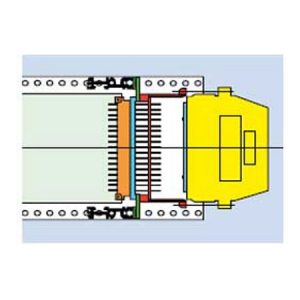 For interface housings with female connector, to attach on the connecting pins of a female connector. Installation in the wiring field of the subrack.
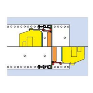 For interface housings with female connector, for mating with a male connector, on Backplane (BP).
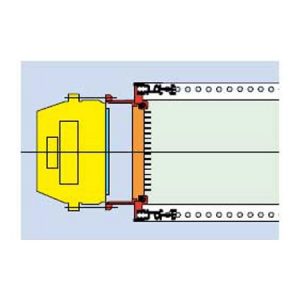 For interface housings with female connector, for mating with a male connector, serves as a handle (GL), mounted on the service side of the subracks.
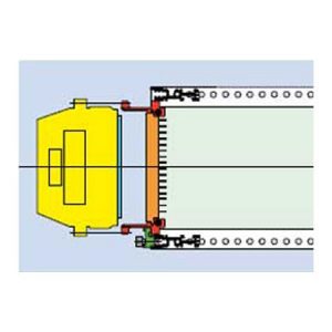 For interface housings with female connector, for mating with a male connector, serves as a handle (GL), mounted on the service side of the subracks.